RST310 9505A IntelliDOCK Docking Station Configuration Manual Beam Communications Pty Ltd 1
RST-100 INSTALLATION AND CONFIGURATION MANUAL RST310 Configuration & Beam Management System Manual Version 2.0 Beam Communications Pty Ltd 8 Anzed Court, Mulgrave, Victoria, 3170, AUSTRALIA Information furnished by Beam Communications Pty Ltd (Beam) is believed to be accurate and reliable. However, no responsibility is assumed by Beam for its use, or for any infringement of patents or other rights of third parties, which may result from its use.
RST-100 INSTALLATION AND CONFIGURATION MANUAL Contents CONTENTS................................................................................................................ 3 CONFIGURING RST310 ............................................................................................ 4 BEAM MANAGEMENT SYSTEM (BMS) ................................................................... 4 INSTALLING THE BMS SOFTWARE ON YOUR COMPUTER ................................................ 4 LAUNCHING BMS...........
RST-100 INSTALLATION AND CONFIGURATION MANUAL POWER MENU............................................................................................................ 4 Enable “No Incoming Calls” Sleep Mode .............................................................. 4 Enable On-Hook Economy ................................................................................... 4 SLIC on................................................................................................................. 4 SLIC off.
RST-100 INSTALLATION AND CONFIGURATION MANUAL Enable .................................................................................................................. 4 Minimum Digits ..................................................................................................... 4 Country Code ....................................................................................................... 4 STD Leading Digit .....................................................................................
RST-100 INSTALLATION AND CONFIGURATION MANUAL Configuring RST310 This chapter describes how to configure the RST310 at initial installation at a site as well as accessing specific Menu items of the unit during routine operation when required. Accessing these menu items is best performed using the Beam Management System, BMS. This section covers most of the items that can be configured in the Supervisor Menu of the BMS. The following section will cover: 1. Installation of the BMS software on your PC 2.
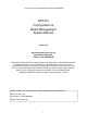
RST-100 INSTALLATION AND CONFIGURATION MANUAL Beam Management System (BMS) In order to configure the RST310 the Beam Management System, software must be installed on your PC/Laptop. Once the BMS is installed you will then connect from your PC to the LOG Port of the RST310 Installing the BMS Software on your Computer The install package comes with 3 files: 1. Setup.exe 2. BMS.CAB 3. Setup.lst To start the install double click on Setup.
RST-100 INSTALLATION AND CONFIGURATION MANUAL If flash magic is not already installed then the install will automatically start.
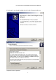
RST-100 INSTALLATION AND CONFIGURATION MANUAL Select directory to install files Select Start Menu folder 9
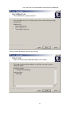
RST-100 INSTALLATION AND CONFIGURATION MANUAL Do not create desktop or Quick Launch icon 10
RST-100 INSTALLATION AND CONFIGURATION MANUAL Do not Launch Flash Magic or view the Release notes OK to finish install 11
RST-100 INSTALLATION AND CONFIGURATION MANUAL Launching BMS From the Start Menu: Select Programs Beam Management System Select Beam Management System 12
RST-100 INSTALLATION AND CONFIGURATION MANUAL Start Using Beam Management System Run the Beam Management System from the start bar. To access the Supervisor Menu of the terminal through the BMS follow these steps. : 1. Reset the RST310 terminal pressing the red reset button on the unit, or alternatively power cycle the unit. This will ensure the PC recognises the terminal.
RST-100 INSTALLATION AND CONFIGURATION MANUAL 2. Open the BMS application on your PC 3. Once the application is running it should ask you to select the Comm. Port from which to operate, it may also allow you to select it automatically. From time to time you may need to restart your computer, as some Comm. ports on PC’s are not as reliable as others. 4. Once the Terminal is found in the display window press OK you will then be able to access the terminal settings and configuration menus. 5.
RST-100 INSTALLATION AND CONFIGURATION MANUAL Supervisor Menu In order to configure the RST310 the Supervisor PIN must have been entered. This PIN is set at factory default to 3170. It is advisable for the PIN to be changed, however be sure to keep a record in a safe place. 1. The Supervisor Menu should be restricted to authorised personnel to avoid inadvertent changing of setting or parameters contained within the unit.
RST-100 INSTALLATION AND CONFIGURATION MANUAL Status Menu The Status menu option provides a current complete status of the RST310 terminal RST310 The Status menu provides a full analysis of the following items. The data can provide a Refresh the status at anytime.
RST-100 INSTALLATION AND CONFIGURATION MANUAL RST State Fault Diagnostics SIM MSISDN Shows the Phone number if preset into the SIM Card LBT IMEI The IMEI ( Serial Number) of the Transceiver module.
RST-100 INSTALLATION AND CONFIGURATION MANUAL Logs Within the Status Menu LOG Tab the call logs can be easily accessed, the call logs provide details of voice calls made from the terminal, as well as tracking any error messages or SMS messages sent from the terminal. RST310 Fetch Log The Call log can be cleared and retrieved from this menu option within the BMS. To get the Log press the Fetch Log button.
RST-100 INSTALLATION AND CONFIGURATION MANUAL Error codes The list of error codes are: Error Code 1 2 3 4 5 6 7 8 9 Error Description The non volatile memory on the RST was invalid on powerup. Parameters are defaults. Some sort of SMS system error. Usually unimportant. SMS error code as PIN. An equipment error reported from the LBT. ME error code as PIN. Over-temperature alarm from RJ11 line interface. ROM checksum error on RST firmware. Continued correct operation in doubt.
RST-100 INSTALLATION AND CONFIGURATION MANUAL Programming Menu RST310 Security Menu Supervisor PINS The supervisor can change the RST310 user PIN as well as their own. The user is able to change their own PIN, but the option is provided here in case the user PIN is forgotten or lost.
RST-100 INSTALLATION AND CONFIGURATION MANUAL User PINS The User PIN is set at factory default to 9876. the user PIN gives limited access to a user to check the status of the terminal, send receive SMS messages and other basic functionality, however it is not possible for the User to access the Supervisor menu functions or configuration. Change RST User PIN Factory default as shipped is 9876. To change User PIN enter the New User PIN and then re-enter it again, then press save.
RST-100 INSTALLATION AND CONFIGURATION MANUAL Flash Upgrade Fill in the entry box with the path and filename of the firmware file you wish to load. You can browse for a file by pressing the “Browse” button. Note: The file must be located in a writeable location. If you received your file on floppy disc or CD we recommend you first copy it to a folder on your hard disc. Note: The computer must be connected directly to the RST in order to program it.
RST-100 INSTALLATION AND CONFIGURATION MANUAL Resets Menu Reboot RST The Reset Menu of the BMS allows you to reboot the RST310 Terminal from the BMS system without having to remove the power or hit the reset switch. This is ideal when the terminal is installed in a secure or difficult to access location. Restore Factory Defaults The Restore Factory Defaults option should only be used when instructed from your support team.
RST-100 INSTALLATION AND CONFIGURATION MANUAL LBT Menu The Start up parameters of the LBT as highlighted in this menu option should be left at the factory default. These should only be configured under instruction form your Service Provider or Beam Technical Support. RST310 This tab exists to reprogram the power-up profile of a particular LBT if it should end up outside the defaults. It should not be modified from defaults without instruction from technical support.
RST-100 INSTALLATION AND CONFIGURATION MANUAL Power Menu The Power Menu option allows for specific configuration of the RST310 terminal to enable the unit to go into power saving modes. These modes may be desirable in some applications whereby the unit is being used in remote environments on Solar Power, and where incoming calls may not be required. Modify these parameters only as directed by your by your Service Provider or Beam Technical Support.
RST-100 INSTALLATION AND CONFIGURATION MANUAL SLIC on How long in ms the loop is powered on each time we check for off-hook. May need to be increased from default if the phone doesn’t reliably detect off-hook in this power saving mode. It will depend on the off-hook load presented by a particular phone(s). SLIC off How long in ms the loop is powered down between off-hook checks. The longer this value the more power saving, at the expense of a longer off-hook detect time.
RST-100 INSTALLATION AND CONFIGURATION MANUAL Settings Menu Data / SIM Settings Timeouts Call Termination The Call Termination parameter enables you to set how long to wait in minutes before terminating a terminal initiated call if there has been no voice or data activity on the line for the specified period of time. This field can be set to 0 to disable this feature and leave a call up forever.
RST-100 INSTALLATION AND CONFIGURATION MANUAL If an incoming data call is received in voice mode and DTR remains high then the RST will switch back to data mode to allow a connected application to answer the data call. Default is 40s to allow for the ATD command. DTR de-assert The DTR De-assert sets how long to observe DTR is de-asserted on the Data port before we switch back to normal voice mode.
RST-100 INSTALLATION AND CONFIGURATION MANUAL CTS de-assert CTS behaviour is only configurable on Hardware revision H.0 or later. When the RST is in voice mode, either because DTR is de-asserted or a Data activity timeout has occurred (see Timeouts Menu), CTS can be programmed to be asserted or de-asserted. De-asserted is more technically correct since the Data port cannot handle characters at this time.
RST-100 INSTALLATION AND CONFIGURATION MANUAL SIM/SMSC Settings Disables PIN lock This function enables the SIM PIN request to be deactivated. This will then enable the terminal to register as soon as it is powered up without requesting the PIN be entered. To disable PIN enter the current SIM PIN and then press disable To enable the SIM PIN again enter the requested PIN and then press enable SMSC (SMS Gateway Number) The SMSC settings are used by the RST when sending SMS’s.
RST-100 INSTALLATION AND CONFIGURATION MANUAL Analog RJ11/POTS Settings Line Settings / Tones / Ringer Configure the RJ11 phone ring frequency and cadence. Frequency On most modern phones frequency change will have no noticeable effect. There are two ON and OFF times (in ms) to allow for a European style RING.RING…… style. For US style cadence set 2nd ON and OFF the same as 1st ON and OFF. 1st ON, 2nd ON, 1st OFF, 2nd OFF All parameters are in milliseconds and change the sound of the ring tones.
RST-100 INSTALLATION AND CONFIGURATION MANUAL Dial tone Using these parameters the dial tone can be set to a Prrrrrr or a Beeeep. For a Beep set the OFF time to 0 and ON to 200ms Frequency Frequency of the dial tone. ON/OFF timers Defines the cadence of the dial tones. Stutter A stuttered dial tone can be optionally generated if there is a Voicemail or SMS waiting so the user can tell this immediately when they pickup the phone.
RST-100 INSTALLATION AND CONFIGURATION MANUAL Unavailable Configure how the network unavailable tone sounds. This tone is generated if the RST is not registered on the Iridium network as yet or Iridium indicates it is unavailable. Normal busy tones are not generated by the RST but by the network. Frequency Frequency of the unavailable tone.
RST-100 INSTALLATION AND CONFIGURATION MANUAL Gain Settings The gain settings of the RST can be configured to suit the installation. All gains are varied by entering in a modifier on the default set gain (for example, –5 dB, +3 dB) since dB is a relative measure. Dial Tone / Signalling Dial tone, Unavailable tone, downlink and uplink voice gains can all be set independently. The gains can be set during a call as the effect is immediate. Uplink The uplink gain should normally be set to 0dB.
RST-100 INSTALLATION AND CONFIGURATION MANUAL Impedance Impedance settings relate to the load the RJ11 phone presents to the RST. As the RJ11 phone line interface is a 2-wire standard, it relies on careful balancing between the impedance expected and experienced by the RST to stop signals in each direction being improperly reflected.
RST-100 INSTALLATION AND CONFIGURATION MANUAL Timeouts DTMF 1st Digit How long to generate dial tone in milliseconds before the 1st digit of the phone number is pressed on the phone. If this time expires it is likely the phone has been left off the hook accidentally and a special rising tone at maximum volume is made to prompt the user to hang-up. DTMF Digit How long to wait for another phone digit before we assume the number has been fully entered.
RST-100 INSTALLATION AND CONFIGURATION MANUAL Activity Sample Period Don’t change this unless you know what you are doing. Adjusts the length of sample window used to determine activity for call termination. Activity Minimum Count Don’t change this unless you know what you are doing. Adjusts how many sounds heard in the activity sample period constitute someone actually talking into the receiver rather than say a door slamming. SMS Ding Optional reminder to the user that an SMS or voicemail is waiting.
RST-100 INSTALLATION AND CONFIGURATION MANUAL Call Processing Enable Turn on/off phone number processing on the RST. To turn on tick the Enable local processing box, top left. Allows local calls to be dialled just as if you were on a normal copper phone line. If disabled most of the settings below have no effect except the voicemail shortcut. Even if enabled, phone number processing can be turned off for a particular number by dialling # first.
RST-100 INSTALLATION AND CONFIGURATION MANUAL STD Leading Digit If the 1st digit of the phone number is this number it is assumed to be national call rather than a local call. The phone number will therefore include the area code to be dialled. Default is ‘0’. Area Code The local area code. Don’t include the STD digit. For example, state of Victoria (in Australia) has an area code of ‘3’, where locally it would be ‘03’ Local Area Code The national area code of the region the terminal is installed.
RST-100 INSTALLATION AND CONFIGURATION MANUAL Iridium Translation Numbers Emergency Local shortcut for emergency services. Commonly set to ‘000’, ‘112’ or ‘911’. Voicemail Local shortcut to retrieve voicemail messages. Default is ‘101’. If this number is dialled, even if call processing is disabled, it is assumed that any waiting voicemails have been retrieved and the voicemail waiting indication (and stutter/ding) is extinguished.
RST-100 INSTALLATION AND CONFIGURATION MANUAL Analogue RJ11 SMSPOTS The Beam SMSPOTS functionality is available on selected Beam RST310 terminals. The SMSPOTS feature enables the use of SMS Compatible POTS type handset. Typically known as a Fixed POTS SMS terminal. POTS SMS Configuration tab Enabling SMS POTS To enable the SMS POTS functionality tick the enable SMS over POTS button in the Beam Management System.
RST-100 INSTALLATION AND CONFIGURATION MANUAL Only selected POTS handsets support SMS sending services. SMS POTS Number Prefixes Note: Many POTS SMS phones instead of displaying International Numbers with a + prefix will instead prefix 00. In replying to such an SMS, the POTS phone will send to a 00… SMS destination. Iridium SMSC’s expect the 00 to be stripped, so the RST does this before passing the SMS on, does not handle this.
RST-100 INSTALLATION AND CONFIGURATION MANUAL Message Send Receive This menu allows SMS messages to be sent to a phone or email destination, allows a Short Burst Data message to be sent to the network programmed SBD destinations or the last SMS received to be observed. SMS destination An International number format phone number (+ not required) or an email address for the SMS destination. Note that two or more email destinations can be used for 1 SMS by putting a ‘,’ delimiter between them.
RST-100 INSTALLATION AND CONFIGURATION MANUAL Send SBD Type in the Short Burst message followed by . The SBD will be sent as an email attachment to the email address set-up when SBD is provisioned. A maximum of 1000 characters allowed. SBD will only be supported by terminals that have been provisioned by the Service Provider. Priority Relative priority on SMS or SBD message. If set to low a voice or data call in progress will not be interrupted.
RST-100 INSTALLATION AND CONFIGURATION MANUAL Advanced Message Settings This tab enables specialised setting of a wake up SMS message for specific applications. When the Enable Wake up SMS is ticked every time the units is power cycled this will automatically send a status SMS message to the predetermined address/destination The Destination address is the address that has been setting the message settings tab.
RST-100 INSTALLATION AND CONFIGURATION MANUAL Online Help The Help button provides similar configuration information as provided in this manual, but will be more up to date as new releases of the Beam Management System are released. Please review the help contents before making changes to a particular setting.