R8/17C PRF+ R40/17C PRF+ en Assembly and Operating Instructions Roller Shutter Drives with integrated radio receiver Wi th plu Ne w co g g : nn a b ec tin le B g c eck ab er le Important information for: • Fitters • Electricians • Users Please forward accordingly! These instructions must be kept for future reference. Becker-Antriebe GmbH 35764 Sinn/Germany www.becker-antriebe.
Assembly and Operating Instructions Table of Contents General........................................................................................................................................................................... 2 Warranty.......................................................................................................................................................................... 3 Safety Information..............................................................................
Warranty Structural modifications and incorrect installation which are not in accordance with these and our other instructions can result in serious injuries, e. g. crushing of limbs. Therefore, structural modifications should only be carried out with our prior approval and in accordance with our instructions, particularly the information contained in these Assembly and Operating Instructions. Any further processing of the products which does not comply with their intended use is not permitted.
Assembly and Operating Instructions • • • • • • • • • • • • • • • • • • • • 4 Important safety instructions for the installation and commissioning Caution! Failure to observe these instructions can lead to serious injuries. Please comply with the safety instructions EN 60335-2-97. Please note that these safety instructions cannot be assumed as being complete, since this standard does not consider all the possible causes of risk.
Intended Use All R8/17C PRF+ to R40/17C PRF+ tubular drives are intended solely for the operation of roller shutters. The tubular drive is fitted with springs which support both the shutter suspension and mechanical anti-lifting devices (e.g. Zurfluh-Feller, Simu, GAH Alberts or Deprat). These are detected automatically. The mains connection cable is not suitable for supporting the weight of the drive. Always support the drive with the housing tube.
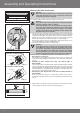
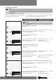
Assembly and Operating Instructions Mounting the roller shutter drive 2 3 4 R8/17C PRF+ to R20/17C PRF+ Self-locking hole Location lug Drive adapter with safety catch Drive adapter R30/17C PRF+ to R40/17C PRF+ Tapped hole M6x12 screw Plain washer Toothed lock washer 5 6 Attention Drives from Becker Antriebe are to be mounted and operated solely with mechanical accessory components shown in the current Becker product catalogue.
4. The drive adapter of the tubular drive is connected to the roller tube as follows: Size of drive [mm] Ø 45 6 7 8 Roller shutter tubes–Ø [mm] 60 - 70 mm plastic or diecast drive adapter Torque max. [Nm] Fastening screws for drivers (4 x) 50 Self-tapping screw Ø 4.8 x 9.5 mm The drive manufacturer also recommends screwing the thrust bearing to the roller tube.
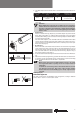
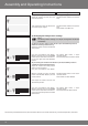
Assembly and Operating Instructions Action Response 1) Connecting the tubular drive 1) + 2a) Mains connection Motor cable blue blue black black brown green/ yellow green/ yellow Connect the tubular drive to the power supply and open the battery compartment of the hand-held transmitter. 2) Activating tubular drive learn mode 2a) Activating the tubular drive learn mode by switching on the power supply Switch on the power supply. The tubular drive goes into learn mode for 3 minutes.
5) Setting the end limits Note The end limits can only be set via the master transmitter. The axle direction setting must be correct. When the end limits are being set, the tubular drive remains in lock-in mode. The lower end limit must always be programmed first. When setting the upper end limit, it is important to ensure that the shutter is securely in the guide rails.
Assembly and Operating Instructions Action Response to 5d) Anti-lifting device at the lower limit to upper stopper 5d) Adjust the shutters until they are in the lower limit position. The tubular drive switches off automatically. Then adjust the shutters up towards the permanent upper stopper. The tubular drive switches off automatically. The end limits have been set. 6) Changing the limit position settings 6a) Note The limit position settings can only be changed via the master transmitter.
Action Response 7) Deleting end limits 7a) Note The end limit settings can only be deleted via the master transmitter. 7a) Deleting the end limits individually Adjust the shutter into the end limit position to be deleted. Clack Clack First press and hold the learn button. Within 3 seconds also press the STOP button and keep both buttons pressed for 10 seconds. The tubular drive makes a “clack-clack” sound to confirm. The end limit has been deleted.
Assembly and Operating Instructions Action Response 9) Ventilation position 9a) Note This function is used to move your roller shutters from the lower end limit upwards in order to open the ventilation slats. The ventilation position can only be set after the two end limits have been set. 9a) Setting the ventilation position Adjust the shutter into the desired ventilation position. First press and hold the STOP button. Within 3 seconds also press the UP button and keep both buttons pressed.
Action Response 11) Deleting transmitters 11a) 11a) Deleting transmitters individually Note The master transmitter which was programmed in point 3) cannot be deleted. It can only be overwritten (see Point 12). Press the learn button on the master transmitter for 3 seconds. The tubular drive makes a “clack” sound to confirm. Now press the learn button of the transmitter to be deleted for 3 seconds. The tubular drive makes a “clack” sound to confirm.
Assembly and Operating Instructions Action Response 12b) Activating the tubular drive programme mode with the radio switch 12b) Clack Slide the radio switch into the inner position. If the radio switch is already in this position, slide the switch outwards and then back to the inner position again. The tubular drive goes into programme mode for 3 minutes. Now press the learn button of the new master transmitter for 10 seconds. The tubular drive makes a “clack-clack” sound to confirm.
Technical Data Type Nominal torque (Nm) Output speed (min-1) Limit switch range Mains voltage Power consumption (W) Nominal current consumption (A) Operating mode Protection class Min. tube diameter (mm) Frequency R8/17C PRF+ 8 17 R12/17C PRF+ 12 17 100 0.45 110 0.50 R20/17C PRF+ 20 17 64 revolutions 230 V AC / 50 Hz 160 0.75 R30/17C PRF+ 30 17 R40/17C PRF+ 37 17 205 0.90 230 1.18 S2 4 Min. IP 44 47 868,3 MHz What should you do, if...? Malfunction Tubular drive is not running.
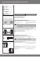
Assembly and Operating Instructions Brief instructions commissioning PRF+ Caution Always adhere to the information contained in the assembly and operating instructions during commissioning, operation and repair work. The manufacturer or supplier shall not accept liability for personal injuries, property damage or consequential damages resulting from non-adherence to the instructions. 1. Connection Connect the wires to the power supply as displayed in the example below.