PARTS & ACCESSORIES Model 7586 Intermittent Pilot Gas Ignition Control Description / Applications The Beckett GeniSys Intermittent Pilot Gas Ignition Control is a 24 Vac gas ignition and safety control. The 7586 is designed for use in residential and light commercial gas heating applications which use an intermittent pilot for lighting the main burner. Applications may include boilers, furnaces, water heaters, space heating and commercial cooking equipment.
Contents Features.......................................................3 Specifications..............................................4 Electrical Ratings....................................4 Electrical Connections.............................4 Environmental Ratings............................4 Approvals................................................4 Lockout Sequence Options.....................4 Timings ...................................................4 Additional Features..............................
Features ◦◦ For use in Natural or LP gas applications ◦◦ 24 volts, 50/60 HZ ◦◦ Can provide either direct flame sense (single rod) through the igniter or indirect (two rod) remote sense using a separate flame rod ◦◦ Field selectable Single or Multiple trials for ignition or Continuous Retry on some models (may be factory locked) ◦◦ Field selectable ignition timings on some models (may be factory locked) ◦◦ Field selectable pre-purge timing on some models (may be factory locked) ◦◦ Field selectable relight
Specifications Electrical Ratings ◦◦ Voltage: 24 volts (18-30 Vac) 50/60Hz ◦◦ Control Current Draw (Run): 0.2 Amps (control only) ◦◦ Pilot Valve Rating: 2.0 Amp ◦◦ Main Valve Rating: 5.0 Amps ◦◦ Note: On models with damper plug but no damper installed, total current draw for all gas valves must be less than 1.75 amps ◦◦ ◦◦ ◦◦ ◦◦ Minimum Flame Current Required: 1.0 µA Flame Failure Response Time: 0.8 sec. (Max.) Control is not polarity sensitive Heat Anticipator Setting: 0.
Installation Professional Service Required Incorrect installation or misuse of this control could result in severe personal injury, death, or substantial property damage from explosion or fire. Read and understand this manual. This control must be installed, configured and put into operation only by a qualified individual or service agency that is: • Licensed or certified to install and provide technical service to gas heating systems. • Experienced with all applicable codes, standards and ordinances.
Mounting The control should be mounted in accordance with the appliance manufacturer’s instructions. If this is a replacement application, mount the control in the same location as the existing control. Mount the control to allow for a short (3 feet or less) ignition cable connection to the pilot burner. The control may be mounted using #8 sheet metal screws or nylon fasteners (if included). Avoid mounting locations where water could drip on the control.
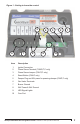
Figure 1 - Getting to know the control 5 6 Item 7 8 4 9 3 2 1 10 Description 1 Igniter Connection 2 Flame Sense Terminal (7586D,T,C only) 3 Flame Sense Jumper (7586T,C only) 4 Reset Button (7586C only) 5 Damper Plug and 24V power for powering damper (7586T,C only) 6 Gas Valve Terminals 7 Burner Ground 8 24V Power & 24V Ground 9 LED Signal Lights 10 Com Port GeniSys Intermittent Pilot Gas Ignition Control Installation and Operation Manual 7
SK10310 Figure 2 - Single Rod or Direct Sense Wiring with Damper Spark Sense (optional) Reset Button (optional) Comm Port TH-W Damper Connector (optional) 24V (optional 24V GND Burner GND MV/PV PV MV Model 7586 Control Status PV Flame MV Vent Damper Controller (Thermostat) Burner GND Alternate Limit Location PV Gas Valve MV/PV/Com MV Pilot/ Igniter Direct Sense Jumper (optional) Burner GND Limit Controller L1 L2 120 VAC Transformer SK10311 Figure 3 - Two Rod or Remote Sense Wi
For single rod sensing applications (sensing through the spark cable), the sensing jumper wire (if present) must be connected to the sense terminal. For two rod sensing applications using a separate flame sensing rod, the wire from the flame rod should be connected to the sense terminal and the jumper wire should be cut and discarded. OEM single rod controls have no sense terminal. OEM two rod controls have a sense terminal but no jumper wire.
◦◦ Following pre-purge (if applicable), spark should be present at the pilot burner. Pilot LED should light. Pilot valve should open. ◦◦ Spark should stay on for the entire ignition timing. ◦◦ Spark should switch off at the end of the ignition timing. Pilot valve and PV LED should turn off. ◦◦ If the control is programmed for single trial for ignition, the Status light will flash rapidly to indicate lockout.
◦◦ If flame is not proved, the control will lockout or enter the inter-trial waiting period. Status LED will flash rapidly for lockout or slowly for inter-trial waiting. ◦◦ If multiple trial logic is used, the control will complete the trials for ignition. ◦◦ If continuous retry logic is used, the control will wait 5 minutes and restart the ignition sequence. The Status LED will flash slowly during waiting period.
Flame Signal Strength Indication Spark Gap The 7586 uses flame rectification to prove the presence of the pilot flame. For reliable operation, a strong flame current is needed. The yellow Flame LED provides a reliable indication of the flame current strength. When the pilot is lit; ◦◦ A continuously on Flame LED indicates a strong flame current. ◦◦ A slowly flashing Flame LED indicates a marginal flame current strength. Consider adjusting the flame on the pilot to improve the flame signal.
LED Key: = OFF = ON = FLASHING For below charts, “Troubleshooting” & “Troubleshooting Sequence” sections. Table 3 - Normal LED Sequence LED STATUS PV FLAME MV LED STATE CONTROL STATE All LEDs off No call for heat or no power to appliance Note: On a call for heat, module will immediately transition to pre-purge or trial for ignition. If pre-purge is set for 1 second, control will move directly to trial for ignition without flashing the Status LED for pre-purge.
Troubleshooting Check LEDs First - Find the box on the left that matches the LED display you are seeing. When all four LEDs are on continuously and the main burner is lit, the system is operating normally. Table 5 - Troubleshooting STATUS PV FLAME MV STATUS PV FLAME MV STATUS PV FLAME MV STATUS PV FLAME MV STATUS PV FLAME MV If the green Status LED is off: ▪▪ No power to the control. ▪▪ Check that the thermostat or controller is calling for heat. ▪▪ Check for power to the appliance.
Table 5 (Continued) STATUS PV FLAME MV STATUS PV FLAME MV STATUS PV FLAME MV If the green Status LED and yellow Flame LEDs are both flashing ▪▪ The control is sensing flame when no flame should be present. ▪▪ The control enters a hold state, this is not a lockout. ▪▪ Control will remain in hold state until flame is no longer present. ▪▪ Check for flame at the pilot. ▪▪ Check gas valve for leakage through the valve, replace valve if leaking.
Pre-purge complete? 1-240 sec. NO ▪▪ Status LED will flash approximately once per second during pre-purge. ▪▪ Wait for the control to complete the pre-purge timing ▪▪ Note: Status LED does not flash for a 1 second pre-purge. YES Trial for Ignition STATUS PV FLAME MV Is the igniter sparking during trial for ignition? NO YES ▪▪ If both Status and PV LEDs are lit, control is in trial for ignition and should be sparking. ▪▪ Check for correct spark gap on igniter.
Troubleshooting (continued) Is the yellow Flame LED on? NO STATUS PV FLAME MV ▪▪ Flame is not being proven, control will lockout or enter waiting period. ▪▪ Check the electrical connections from the control to the flame rod or ignitor sensor. ▪▪ Make sure all connections are clean and free of corrosion or build up. ▪▪ Check the continuity of the ground wire and the sense wire or ignition cable. ▪▪ Flex ignition cable while checking continuity to check for intermittent connection.
Page intentionally left blank 18
Page intentionally left blank GeniSys Intermittent Pilot Gas Ignition Control Installation and Operation Manual 19
Limited Warranty Information The R. W. BECKETT CORPORATION (“Beckett”) warrants to persons who purchase its “Products” from Beckett for resale, or for incorporation into a product for resale (“Customers”), that its equipment is free from defects in material and workmanship. To qualify for warranty benefits, products must be installed by a qualified service agency in full compliance with all codes and authorities having jurisdiction, and used within the tolerances of Beckett’s defined product specifications.