RESIDENTIAL BURNERS Potential for Fire, Smoke and Asphyxiation Hazards Incorrect installation, adjustment, or misuse of this burner could result in death, severe personal injury, or substantial property damage. To the Homeowner or Equipment Owner: y Please read and carefully follow all instructions provided in this manual regarding your responsibilities in caring for your heating equipment. y Contact a professional, qualified service agency for installation, start-up or service work.
To the Owner: Thank you for purchasing a Beckett burner for use with your heating appliance. Please pay attention to the Safety Warnings contained within this instruction manual. Keep this manual for your records and provide it to your qualified service agency for use in professionally setting up and maintaining your oil burner. Your Beckett burner will provide years of efficient operation if it is professionally installed and maintained by a qualified service technician.
Section: General Information General Information Hazard Definitions Indicates a hazardous situation, which, if not avoided, will result in death or serious injury. Indicates a hazardous situation, which, if not avoided, could result in death or serious injury. Indicates a hazardous situation, which, if not avoided, could result in minor or moderate injury.
Section: Inspect/Prepare Installation Site Impaired Burner Performance and Fire Hazard. Do NOT operate the burner beyond specifications outlined in the following Table. Special Requirements ○ y For applications beyond these limits, consult Beckett Technical Service at 1-800-645-2876. ○ y NOTE: Some packaged appliances with burners may be agency listed as a unit to operate beyond these limits. Consult the appliance manufacturer’s specifications and agency approvals for verification.
Section: Inspect/Prepare Installation Site Table 2 – Air Tube Combinations (ATC) & Dimensions Head Design - Fixed Adjustable w/stop screw Head Design ATC codes for usable air tube lengths dim. “A” (Figure 3) 3” 5” 7” 9” HLX30 HLX50 HLX70 HLX90 HLX30 HLX50 HLX70 HLX90 HLX30 HLX50 HLX70 HLX90 HLX30 HLX50 HLX70 HLX90 FBX30 FBX50 FBX70 FBX30 FBX50 FBX70 FBX30 FBX50 FBX30 FBX50 AFII 85 AFII 100 AFII 150 HB AF2-6 0.4-0.85 gph 0.65-1.00 gph 0.75-1.35 gph HC AF2-9 N/A 0.
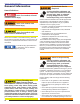
Section: Inspect/Prepare Installation Site Eventually the blockage could prevent exhausting the flue gases. Instead, the flue gases could vent out the barometric damper into the living space. the burner or provide a sealed enclosure for the burner and supply it with its own combustion air supply. Therefore, it is strongly recommended that an approved insulated stainless steel liner be installed.
Section: Prepare the Burner ○ On the outside of the home use a 90° elbow pointed downward with a 1/4” mesh screen over its opening. The air inlet elbow must be located above the snow line and in such a way as to prevent leaves and/or other debris from blocking the air flow. Such debris will prevent proper operation of the burner. Refer to local codes for proper location of inlet. Figure 4.
Section: Mount Burner on Appliance & Wire Burner Mount Burner on Appliance Verify that the air tube installed on the burner provides the correct insertion depth. Refer to Figure 6. Wire Burner Burner packaged with appliance Figure 6. – Mounting Burner in Appliance Electrical Shock Hazard Electrical shock can cause severe personal injury or death. y Disconnect electrical power before installing or servicing the burner.
Section: Burner Controls Burner Controls Wiring GeniSys Model 7505 Control Fire or Explosion Hazard Can cause severe injury, death, or property damage. y The control can malfunction if it gets wet, leading to accumulation of oil or explosive oil vapors. y Never install where water can flood, drip or condense on the control. y Never use a control that has been wet - replace it.
Section: Burner Controls Typical Burner Sequence of Operation for GeniSys 7505 Control. Refer to the appliance manufacturer’s wiring diagram for actual specifications. 9 1 Pump prime Standby 3 2 4 Trial for ignition Valve-on delay Lockout 5 Ignition carryover 6 8 Motor-off delay 1. Standby: The burner is idle, waiting for a call for heat. 2. Valve-On Delay: The igniter and motor are on while the control delays turning on the oil solenoid valve for the programmed time. 3.
Section: Burner Controls 60 70 SAFETY AND OPERATING LIMITS L1 R L2 60 70 60 70 W SAFETY AND OPERATING LIMITS 80 50 60 50 80 L2 W 80 50 L1 Figure 8b. – Interrupted ignition, valve-on delay and motor-off delay 70 R 50 80 Figure 8a.
Section: Burner Controls Figure 9 - Typical Burner Wiring & Burner Sequence of Operation for R7184P Control. Refer to the appliance manufacturer’s wiring diagram for actual specifications. 1. STANDBY. The burner is idle, waiting for a call for heat. When a call for heat is initiated, there is a 310 second delay while the control performs a safe start check. 2. VALVE-ON DELAY. The ignition and motor are turned on for a 15 second valve-on delay. 3. TRIAL FOR IGNITION (TFI). The fuel valve is opened.
Section: Start Up Burner and Set Combustion Wire Burner Some Thermostats Are Polarity Sensitive. Reversed polarity could cause erratic cycling of the burner control. Connect the wire from the RH or R terminal on the thermostat to the TR terminal on the control. Connect the wire from the W terminal on the thermostat to the TW terminal on the control. ○ ○ ○ Make connections to the control’s terminals as shown in Figures 8a and 8b. Refer to the label on the underside of the control for wiring details.
Section: Perform Regular Maintenance ○ Natural Draft Applications; typically over-fire draft is -0.01” or -0.02” w.c. The following guidelines are provided for routine maintenance. ○ Direct Venting; typically may not require draft adjustment. □ Replace the oil supply line filter. The line filter ○ High Efficiency/Positive Pressure Appliances; also vary from traditional appliances (see manufacturer’s recommendations). □ Inspect the oil supply system. All fittings should be 3.
Section: Perform Regular Maintenance 1. Turn off power to burner before proceeding. Shutting the Burner Off Always keep the fuel oil supply valve shut off if the burner(s) is shut down for an extended period of time. Turn off all electric power to the burner. Note: There could be more than one disconnect switch.
Section: Perform Regular Maintenance 10. If the head was removed when replacing the nozzle, carefully reconnect the head to the nozzle adapter. Push the head support until it stops against the nozzle shoulder. Verify the dimension between the nozzle face and the back of the head is 5/32”. Figure 11a. Electrode Settings-HLX Air Tube Combinations 3/32” 1-1/2” Do NOT overtighten Clamp Screw Stop Screw Figure 10a.
Section: Perform Regular Maintenance HLX Firing Rate Stop Screw AFII 85 AFII 100 AFII 150 0 0.40-0.65 0.5-0.65 0.75-1.00 1 - 0.6-0.75 0.85-1.10 2 - 0.65-0.80 0.95-1.15 3 0.60-0.75 0.65-0.90 0.95-1.20 4 - 0.75-0.95 1.10-1.25 5 0.70-0.85 0.85-1.00 1.15-1.35 6 - 0.95-1.10 1.15-1.40 7 - - 1.25-1.50 8 - - 1.30-1.50 HLX Air Dial Setting Firing Rate @ 140 psig AFII 85 AFII 100 AFII 150 0.40-0.65 3 - - 0.60-0.75 4 3 - 0.70-0.85 5 4 - 0.75-1.00 - 5 2 0.
Section: Replacement Parts Replacement Parts For best performance specify genuine Beckett Item Description replacement parts Kit No. Item Description Kit No.
Limited Warranty Information The R. W. BECKETT CORPORATION (“Beckett”) warrants to persons who purchase its “Products” from Beckett for resale, or for incorporation into a product for resale (“Customers”), that its equipment is free from defects in material and workmanship. To qualify for warranty benefits, products must be installed by a qualified service agency in full compliance with all codes and authorities having jurisdiction, and used within the tolerances of Beckett’s defined product specifications.