FOR THE PROFESSIONAL SERVICEMAN to at D_tt_buted as (t,_z iru4ustrtj service b_
FOR THE PROFESSIONAL SERVICEMAN at R/C,: Beckett Corporation 38251 Center Ridge Road P.O. Box 1289 Elyria, Ohio 44036- !289 1-800_OIL BURN (645-2876) R.W, BeckettCanada, Ltd.
Acknowledgements R.W.Beckett Corporation is pleased to present this new, revised edition of Guide to Oilheat for the ProfessionalServiceman (formerly known as The ProfessionalServiceman's Guide to Oilheat Savings). This new edition has been expanded to include updated information and several additional topics of importance to the industry as we approach and enter the 21st Century. These topics include direct, side-wall venting and outside combustion air.
Acknowledgements VCewish to acknowledgeand thank the followingcompanies and organizations (listedalphabetically)that suppliedillustrations, photos, and/or information used in the revised edition of this book: Bacharach,Inc. Broo'yahaven NationalLaboratory DanfossAutomatic Controls DelavanInc. FieldControls HagoManufacturing LynnProductsCo. PetroleumMarketersAssociationofAmerica $untecIndustriesIra:. Testo,Inc. Thermo-DynamicsBoilerCo. TjernlundProducts,Inc. Trianco-Heatmak_r, Inc.
TABLE OF CONTENTS CHAPTER 1 COMBUSTION THEORY ................................................................................................. Fuel Oil ............................................................................................................................. Combustion ....................................................................................................................... Role of Excess Air in Combustion ..................................................................
LIST OF FIGURES FIGURE PAGE FIGURE PAGE 1 Viscosity vs. temperature, No. 2 fuel oil .......... 1 38 Power chimney venting system ..................... 26 2 "viscosityconversion, Centistokes vs. Saybolt Universal Seconds ............................................. 1 39 Efficiency vs. net stack temperature ............... 26 40 3 Combustion products by weight and volume, 1 lb. fuel oil, 0% excess air ............................... 3 Common chimney troubles and theircorrections .................
Purposeof Manual This manual has been prepared for use by oilheat service managers and service technicians_ It provides a brief overview of oilheat systems, as well as a review of basic oil burner combustion theory. Included are suggested procedures for adjusting and maintaining oil burners-and oilheat system components-to other provide your customers with maximum efficiency, comfort, and safety.
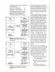
CENT1STOKESvs.SAYSOLTUNWERSAL SECONDS VISCOSITy"CONVERSION ATi 00' F 5 This chapter reviews the basic concepts about the process of combustion. You should understand this process before tackling the other chapters in this manual! It's likely that a good deal of material presented is familiar to you, but there's an even better chance that you might learn something new. It's worth reading, since this information develops the foundation from which every dependable oilheat service technician should work.
turetestisvaluable. It consists offueloilbeing heated gradually inaflaskuntilitvaporizes, then iscondensed intoagraduated cylinder. The temperature atwhichcondensation begins is calledtheinitialboilingpoint(IBP).Therising temperature isrecorded foreachfraction distilled. It isusuallyreported in 10%increments untilthe finaldropisrecovered orendpointisreached. Theinitialboilingpointcouldcause ignition problems if it istoohigh(over400°F).
indicating that nitrogen does not participate in the reaction. Consequently, because of the These reactions can be rewritten using symbols in the following manner: C+O2+N 2 -_ CO2+N2+heat (1) 2H2+O2+N 2 -_ 2H20+N2+heat (2) large amounts of nitrogen in the air, the bulk of the flue gas is made up of unreacted nitrogen. Note: Some nitrogen does react with oxygen to create a small amount of nitrogen oxides or NOx. Both chemical reactions produce entirely new products, and each reaction gives off heat.
24 ! 22 03 < O ILl 20 16 z 14 O O Z LI.I 0 II LU I3u I I ! ! _ 18 -J It. ! MEASURE PERCENT CO 2 TO D_ERMINE PERCENT EXCESS AIR 12 10 8 6 _" _IIii _._,m_mi " .iii-- 4 2 0 l 0 i0 20 3o 4o so eo 7o 8o 90 i30 i40 1;50 PERCENT EXCESS AIR FIGURE 5 Relationship between excess air and CO2 In Figure 4, since 20.9 percent of the excess air is oxygen, 7.1 percent of all the combustion gases is oxygen. You determine this by multiplying the percent excess air (33.
Also,bylookingatFigure6youcanseethatthe coffeeexample illustrates theeffectofexcess air (shown aswater)in dilutingthegas(coffee) and theresulting reduction intheCO2 percent. Bearin mindthatthistemperature reduction and dilutiontakesplaceinthecombustion zone,not intheflueorstack. It is important tonotethatthe effectofexcess aironthetemperature oftheflue gasisdifferent. Withmoreexcess air,thefluegas temperature tends to rise.
Excess combustion air reduces heating plant efficiency. Too much smoke will eventually reduce efficiency also. Unfortunately, as you have learned, as the amount of excess air is increased, the transfer of heat to the heat exchange medium (hot water, warm air, or steam) is reduced.
OILHEAT SYSTEMS OVERVIEW OF OILHEAT SYSTEMS The primapy emphasis of this manual is on oil burners. However, a brief look at total oilheat systems would be appropriate. Maximum heating efficiency, reliability, and safety cannot be achieved unless all components of the system are Storage Tanks Residential fuel oil storage tan_ksfall into three categories: underground, above ground, and indoor. Each has i_ advantages and disadvantages. Underground Tanks compatible and in top working condition.
Disadvantages: (1) Exposed to cold and moisture. (These problems can be reduced by providing a shelter for the _k.) can be installed. Always follow burner (2) Take up outdoor space. Oil Burners (3) May detract from appearance of home. The functions of an oil burner are to break fuel oil Indoor Tanks into small droplets, mix the droplets with air, and ignite the resulting spray to form a flame. manufacturer's instvactions when adjusting oil pressure or installing heaters.
Draft Regulators Many flue pipes include a barometric draft regulator. This consists of a counterweighted swinging door which opens and closes to help maintain a constant level of draft over the fire. Modern high-speed, flame retention burners are much less sensitive to changes in natural draft allowing draft regulators to be eliminated in some cases. However, check the burner manufacturer's instructions, and local codes, before eliminating draft regulators. See page 22 for more details.
Combustion Heads The combustion head (also referred to as the turbulator, fire ring, retention ring, or end cone) creates a specific pattern of air at the end of the air tube. The air is directed in such a way as to force oxygen into the oil spray so the oil can burn. Flame Retention Heads vs. Non-Flame Retention Heads c The majority of combustion heads in the field today are flame retention heads.
Generally speaking, it is advisable to choose a flame retention head over a non-flame retention head in the majority of applications. There are a few existing heating units in the field which have used a non-flame retention head in a steel chamber. These units can be retrofitted with a new burner and non-flame retention head, or could use a flame retention head with the addition of a chamber liner for protection against the hotter flame temperatures produced by the flame retention head.
providing heat can cause discomfort for home or building occupants, precipitate nuisance service calls, and have a negative effect on fuel efficiency. To supply heat quickly, the burner flame must ignite instantly and smoothly. It requires adequate airflow (draft) to accomplish this. Typically, when an oil burner has been off for a while, natural draft in the chimney can become neutral. Cold chimneys contain heavy air that must become heated and start to flow upward before draft can occur.
When replacing nozzles, it is usually best to use a nozzle identical to the one supplied as original equipment by the burner manufacturer. Consult burner manufacturer specifications whenever possible. If these are unavailable, a call to the manufacturer might be advisable. Do not assume that the nozzle currently in use is the correct one. It may have been installed in error during a prior burner servicing.
the combustion chamber without actually touching any part of the chamber surface. Be sure to follow specifications manufacturers. provided by Good Combiner;on COMBUSTION CHAMBERS The function of the combustion chamber is to surround the flame and radiate heat back into the flame to aid in combustion. The combustion chamber design and construction helps determine whether the fuel will be burned efficiently.
and the oil has not been heated up to maximum temperature at this point. (See Figure 19.) Modern flame retention burners are not as dependent on chamber shape. A well designed chamber will confine the flame, and more reflected heat will enter the combustion process in its early stages. This will aidcombustion and provide much smootherignition.
FIGURE 21 Soft fiber refractory combustion chambers Although it is possible to obtain a relatively good fire without a chamber, you should realize that a properly sized and shaped combustion chamber will substantially improve combustion, provide a hotter flame, and reduce the amount of soot accumulation associated with sta_ up and shutdown. Large commercial burners are frequently fired without a chamber, but with small residential burners the chamber becomes extremely important.
Square Square InchArea Combustion Consumption Combustion Chamber Chamber Inches gph Oil 0 Sq. In. erGal, 90 Sq. In. Per Gal. 100 Sq. In. Per Gal. HEIGHTFROMNOZZLETO FLOORINCHES Die.Round Rectangular Combustion Combustion Conventional Conventional Sunflower Sunflower Chamber Chamber Burner FlameBurner FlameBurner Burner Inches Inches Widthx Length SingleNozzle SingleNozzle TwinNozzle .75 .65 1,00 1.25 1.35 1.50 1.65 2.00 2.50 3,00 60 68 80 100 108 120 132 160 200 240 8x8 8.
HEAT EXCHANGERS The next step in the operation of the heating Heat appliance is the transfer of heat energy from the combustion gases to the air in the furnace or to the water in the boiler. This is accomplished in the heat exchanger, which is simply a wall which Many types of heat exchangers--with varying degrees of efficiency--are in use today. The following are some major types: keeps gases or liquids separated and allows heat energy to flow out of the hot medium and into the cooler medium.
Heat Exchangers Primary 3econdary [ 11 Condensing 1 Ai Handler FIGURE 25 Oil furnace heat exchanger q_ FIGURE26 Condensing furnace heat exchanger prolonged gas/exchanger contact, to capture more of the heat. (See Figure 25.) "O Condensing Furnace Exchangers Condensing furnaces have three separate exchangers: the primary 11,000 i o,ooo"6 exchanger, the secondary exchanger, and a condensing exchanger which cools gases t..
volume of combustion gases produced per unit of time. Figure 27 indicates the relationship between excess air and the flame temperature and volume of combustion gases. openings. The openings must connect with the inside of the building, which should have adequate infiltration from the outside. Insulation is any material that stops or slows down the normal rate of heat transfer. Obviously, you do not want to place an insulating material between the combustion gases and the heat exchanger walls.
Ii Residential system The Tjernlund Combustion Air In-ForcerTM mechanically drawsoutside air indoors on demand to providefresh air for safe and efficientoperationof fuel burning equipment,withoutrequiringdirect connectionto the appliances. The commercialsystemblendscoldair withambient roomair before dischargingin the home or building.
Outside Condition Inches W:C. Winter start up 20 110 -.050 Winter operation 20 400 -.136 Fall start up 60 8O -.011 Fall operation 6O 400 -.112 FIGURE 30 Exampleof draft changesin a chimney V Chimneys may not draft correctly due to problems such as the following: A. Chirvmey is too big (See Figure 32, page 24). B. Breaks in the chimney liner. C. An improperly constructed or damaged flue system venting multiple appliances to a common chimney (See page 24).
FIELD DRAFT CONTROLS TYPE RC TYPE M Oil or Coal Residential Oil or Coal Residential and Commercial Designedforsettingsfrom.01" to.l". Recommendedfor oil or coal fired Calibratedto alloweasy adjustmentto furnace or boiler residentialheatingapplications. manufacturer's specifications. Featuresan infinitelyvariable screw Designedfor settingsfrom .02"to adjustment,permitting an extremely .08". It is sosensitivethat fine instrumentsetting. instrumentation shouldbe usedfor adjustments.
Flue and Chimney Venting Multiple Appliances a Common Chimney or Flue Exhaust 1. Flue Pipe The flue pipe should be the same size as the breech connection on the heating plant. For modem oilheat units, this should cause no problem in sizing the flue pipe. The sizes generally are 4" to 6" under 1 gph, 7" to 1.50 gph, and 8" for 1.50 to ZOOgph. The flue pipe should be as short as possible and installed so that it has a continuous rise from the heating plant to the chimney.
Whether youarecombining twoappliances or more,youwill followthesame method of totalingindividual fluesizestodetermine your mainflueormanifold. Common Systems Figures 35 and 36 show the most common types of multiple appliance venting systems the tapered manifold system and the constant sized manifold system. When determining the sizing for the tapered manifold system (Figure 35), size each section according to the combined input of the appliances that vent through that section.
Benefits The first benefit of a side-wall venting system is that it eliminates the need for a chirrmey. This can result in potential savings in new home construction. There is also the opportunity to retrofit chimneyless (i.e., electrically heated) homes. The second benefit is the potential for increased efficiency.
FIGURE 40 Common chimneytroubles and theircorrections Troubles Examination Topofchimney lower thansurrounding objects. Observation, Chimney caporventilator, Observation, Corrections Extendchimneyabove allobjectswithtn 30feet. Remove. Coping restricts opening. Observation. Makeopeningaslargeas inside ofchimney. Obstructionin chimney. Can be foundby lightandmirror reflecting conditionsin chimney. Useweight tobreakand dislodge. Joist projectinginto chimney.
to ensure proper draft from the induced draft fan. Temperature sensing switches can be utilized as backup protection for a blocked vent condition. Side-wall fittings must be designed for walls constructed of combustible materials. The sidewall presence of flue products at 200°F-300°F must be considered. Reliable operation is a second concern. Wind direction and velocity can have a great impact on a side-wall exhaust vent and must be considered both in system design and in installation.
Power Venting Outdoor Units In this type of system, a power draft inducer fan is used as with power chimney venting. However, the gases are vented through the wall rather than up a chimney. If the fan is inside the house, any When the appliance itself is outside the home, portion of the system between the fan and the outside vent is under a positive pressure and must be carefully sealed to prevent gases from leaking into the house.
% DEFINITION OF VARIOUS TYPES OF EFFICIENCY When the word efficiency is used, do you know what is meant? By definition, efficiency is a measure of how well something is produced as compared with what went into producing it. In terms of heating systems, efficiency is a measure of how well energy is transferred from one form or place to another form or place.
These ratings mightbecompared tothemileage ratings forautomobiles. The"steady" highway drivingMPGratingis always higherthan the city or "average" driving MPG rating. In both instance the AFUE and MPG ratings were obtained under very carefully controlled laboratory conditions. There are important reasons why the actual fuel consumption experienced in the field will be slightly higher. There are many variables that occur throughout the heating season that can impact on the overall system efficiency.
method of efficiency measurement, is used. MEASUREMENTS The stack loss method is based on three This chapter covers the proper use of instruments to measure the steady state efficiency of residential oil-fired heating appliances. Since you should 1. All the chemical energy in the fuel is converted to heat energy.
measuring the percent carbon dioxide, you not only can determine how much excess air exists, To measure the heat lost through the flue and chimney you must: but also you can determine the weight of combustion products flowing up the flue pipe. V Determine the amount of the combustion gases per gallon of fuel oil burned.
Once you know the percent CO 2 or oxygen and the net stack temperature, you can determine the steady-state efficiency based on the stack loss method. Remember that the stack loss will be determined per gallon of fuel oil burned, since this is how the weight of the combustion gases was measured. Because of this, you don't have to measure the fuel input into the burner.
RGURE 49 No. 2 fuel oil efficient-t table Net Stack Temp. oF %02 200 250 300 350 400 450 500 550 600 650 700 750 800 _02 1 89.6 88.4 87.3 86.2 85.1 84.0 82.9 81.7 80.6 79.5 78.4 77.3 76.2 14.7 2 89.4 88.2 87.0 85.9 14.0 3 89.2 87.9 86.7 85.5 84.3 83.1 81.9 80.7 4 88.9 87.7 86.4 85.1 5 88.7 87.3 86.0 84.6 83.3 82.0 80.6 79.3 i77.9 76.6 75.3 73.9 72.6 11.7 6 88.4 87.0 85.5 84.1 82,7 7 88.0 86.5 85.0 83.5 82.0 84.7 83.6 82.4 81,2 80.1 78.9 77.7 76.6 75.4 79.4 78.2 77.0 75.
Measurement Carbon Dioxide of or Oxygen Historically, to deterroJne the weight of the combustion gases per gallon of fuel oil burned, carbon dioxide has been measured with equipment like that shown in Figures 47 and 50. This is a rugged, inexpensive, and easy-to-operate device. However, if you recall from Chapter 1, the percent oxygen also can be used to detenmne the weight of the combustion gases.
V Allow instrument to reach room temperature. If you have just come in from the cold outdoors, place the Fyrite in a warm location such as near the boiler or furnace. Make sure it is not too hot, and don't forget to remove the instrument. Y Make sure sufficient liquid is in the reservoir. If the liquid level is low, add water to the top of the reservoir and depress plunger valve. Repeat until scale can be adjusted to the height of the liquid level.
Alternative Measurement Techniques Lynn Combustion Efficiency Analyzers. Lynn Products Company manufactures a line of Combustion Efficiency Analyzers that measure 0 2, flue temperature and smoke level. The instruments employ an electrochemical oxygen sensor that produces a small electrical current proportional to the level of oxygen.
Bacharach CA 40H Combustion Analyzer (hand-held) measures and displays 0 2, CO, draft, air temperature, and stack temperature while simultaneously computing and displaying combustion efficiency, net stack temperature, CO 2, excess air, and CO referenced to 3% 0 2. An advanced version stores up to 100 tests in merr_gry and downloads to a computer through a built-in RS 232 port. RGURE54 Fluegasthermometers The thermometer should be inserted to the approximate mid-point of the stack.
There are other devices that cart be used to measure the flue gas temperature such as mercury-filled glass thermometers or thermocouples with potentiometers. Don't even consider a glass thermometer for other than calibration use, and even then it's risky! They are fragile and easily broken and, furthermore, mercury vapor is hazardous. Thermocouples, however, are a possible alternative to dial thermometers; they are accurate, have a quick response to temperature change, and are easy to use.
pletely in. Repeat the stroking procedure ten times. This allows an exact volume of gas to be passed through the filter paper. When the filter paper is removed, the amount of soot which has been filtered onto the paper will leave a circular colored spot. The darkness of the "smoke spot" is then compared against a Bacharach Oil Bumer Smoke Scale (a scale from 0 to 9 representing increasing shades of darkness). If there is no soot, the paper will be white colored.
also easy to use. The Draftrite is a slim, hand Carbon held, rectangular device with a curved draft scale placed behind a free floating pointer. The back of the device has an opening in which short metal tubes screwed in series can be inserted. The end There is little chance of dangerous levels of carbon monoxide being produced by a properly installed, properly adjusted, well-maintained oil heat system which is supplied with adequate combustion air.
FIGURE59 COlevelstandards CO Level Standards The following standards were in effect at the time this book was edited (1997): ASHRAE American Society of Heating, Refrigerating Standard 62-89 and Air Conditioning Engineers - ASHP_E states the ventilation air shall meet the outdoor air standard. See U.S. EPA standards below. EPA Environmental Protection Agency EPA recommends 9 ppm or lower as an ambient air quality goal averaged over eight hours.
RESIDENTIAL OIL BURNER ADJUSTMENTS Now that you have reviewed the basics of combustion, combustion efficiency, and the operation and use of measurement equipment, you are prepared to study testing and adjustment procedures. The first and most important procedure is the proper adjustment of the burner, whether it be for an annual tune-up, the installation of a new flame retention burner, or the reduction of a firing rate.
Correlation of Percent of CO 2, 0 2 and Excess Air Carbon Dioxide Oxygen Excess Air (approx.) I5.4 0.0 0.0 15.0 0.6 3.0 14.5 1.2 6.0 14.0 2.0 10.0 13.5 2.6 15.0 13.0 3.3 20.0 12.5 4.0 25.0 given to item 4 above. In dry-base boiler models and furnaces, the refractories are 12.0 4.6 30.0 11.5 5.3 35.0 selected to withstand the elevated tempera- 11.0 6.0 40.0 tures of high performance burners.
tion, which could possibly produce high emissions of carbon monoxide and unburned E. Adjustment of Electrodes. Adjust ignition electrodes according to burner manufacturer's instructions to assure prompt ignition. hydrocarbons. When retrofitting in older appliances, this condition can sometimes be F. Operate Burner.
RECORDING OF READINGS THE ANNUAL CLEAN-UP Now that you've performed your adjustment, record the readings on a form similar to that shown in Figure 63. This will be left to inform We strongly recommend that the following procedures be performed each year in advance of the heating season: the homeowner of the measurements you made. This type of information is important for homeowners to receive. It improves your image and indicates to the homeowner that you and your company are responsible and thorough.
G. Service the Burner Make sure the power is off. 2. Remove the pump strainer cover and clean strainer. Replace cover gasket. Secure cover. 3. Replace oil filter element, leaving the canister clean and tight. Sludge or water means the _'ak needs to be checked for the cause. Assure oil lines are clean, straight and all fittings are leak-free. Use flare fittings; never compression fittings. 4. Remove the firing assembly. Clean internal tubing. Check electrode porcelains for cracks.
FIGURE 63 Testreportform The following test results are based upon measurements of your heating system performed on date i Efficiency (%) Smoke CO2 (%) OR 0 2 (%) Gross Stack Temperature (°F) Room Temperature (°F) Net Stack Temperature (°F) Overfire Draft Stack/Breech Inches W.C, Draft Inches W.C.
BASIC TROUBLESHOOTING Recommended Equipment 1. Electrical test meter (VOLTS, OHMS,AMPS). 2. Ignition transformer tester, 3. Combustion analyzerkit (oxygen orcarbon dioxide, smoke, stack temperature, draft, system efficiency). 4. Pressure/vacuum gauge (0-200 psig and 0-30: Hg). 5. Full assortment of standard hand tools. . Reset primary contro! if necessary. Run several cycles. Observe flame quality. Use a flame mirror, if possible, to see if flame base is stable and close to combustion head.
This information is usually printed on the control body Erratic operation may be caused by improper anticipator settings. Settings are typically .2 or .4 amps. This value can usually be measured by connecting a multitester in SERIES with one of the Tr leads, and reading the value on the appropriate milliampere scale. The Ignition System is generally comprised of an ignition transformer and two electrodes that deliver a concentrated spark across a fixed gap to ignite oil droplets in the nozzle spray.
OPTIONS This manual is intended to provide you with information that can aid you in performing energy conservation modifications on residential oil-fired heating equipment. A sound understanding of the fundamentals of combustion theory is essential. Also, a full understanding of the significance of instrument measurements and their proper use is an integral part of analyzing all energy conservation options.
Non-Flame Retention Flame Combustion Retention Combustion Nozzle Nozzle Combustion Air CombustionChamber _\ Combustion Chamber (Optional) Non-Flame Retention Rear V_ew Cast Iron Target Wall Rame Retention Combustion Head Rear View Stainless Steel Circumferential Slots r Vanes Combustion Head Radial Vanes FIGURE 65 Non-flame retentionand flame retention combustion higher overall efficiency. More useable energy is capacities of .
AFII AIR TUBE COMBINATION AND FIRING RATE CHART FIRING RATE RANGE AFII 85 Head Design - Adjustable H_50 HLX30" H_50 HLX30 L HLX50 HLX30 HLX50 Head Desl w/stop screw - typical HUX70 HLX90 ' HLx70" Hffxg0 _ HLX70 H_70 H_90 HLX90 AFII 150 AF2-6 AF2-9 .4-.85 GPH N/A ,75-1.35 GPH ,75-1.50 GPH ...... HD HE AF2-6 AF2-9 .4-,85 GPH t_A .75-1.10 GPH .75-1.
sales business. Unforpanately, not all homeowners will take your advice, and some homeowners presently can't afford the cost of a new burner, Also, it is much more cost effective to replace a burner operating at 55 percent efficiency than a burner operating at 73 percent.
RGURE 70 Outdoor winterdesign temperatures Outdoor Winter Design Temperatures (°F / Dry-Bulb)* Source: 1993 ASHRAE Handbook - Fundamentals State City 99% 97.5% ALASKA AnchorageAP Fairbanks AP JuneauAP NomeAP -23 -51 -4 -31 -18 -47 1 -27 CONNECTICUT Bridgeport AP Hartford,BrainardField NewHavenAP NewLondon Norwalk Norwich Waterbury 6 3 3 5 6 3 -4 g 7 7 9 9 7 2 DELAWARE DoverAFB WilmingtonAP 11 10 15 14 DISTRICTOF COL. AndrewsAFB Wash.
FIGURE 70 Outdoor winterdesign temperatures Outdoor Winter Design Temperatures (Continued) (°F / Dry-Bulb)* Source: 1993 ASHRAE Handbook - Fundamentals State City 99°/o 97.
NOZZLE MANUFACTURERS AND SPRAY PATTERNS DANFOSS DELAVAN HAGO MONARCH STEINEN AS-SOLID A-HOLLOW ES-SOLID R-SOLID S-SOLID AH-HOLLOW B-SOLID P-SOLID NS-HOLLOW AB-SEMI-SOLID W-ALL PURPOSE SS-SEMI-SOLID AR-SPECIALSOLID SS-SEMI-SOUD H-HOLLOW PLP-SEMI-SOLID SS-SEMI-SOLID H-HOLLOW PL-HOLLOW NOZZLE CAPACITIES U.S. Gallons rate gph @ 100 psi per Hour No. 2 Fuel Oil Operating Pressure: pounds per square inch ................ 140 150 175 250 275 300 .45 .56 .67 .73 A7 .59 ,71 .
Call the Beckett Service Hotline You can really expect more from Beckett. 0 5 FormNo. 6380 R97 © 1997R.W.Beckett Corporation Printed in U.S.A.