Installation, Operation and Maintenance Manual Oil Fired Warm Air Furnaces O4HD-091A-12-FB (Up-Flow Model) O4HD-091A-14-FA-DV (Up-Flow Model) O4HD-091A-V-FA (Up-Flow Model with ECM) FOR YOUR SAFETY: Do not store or use gasoline or other flammable liquids or vapors in the vicinity of this, or any other appliance. ALL INSTALLATIONS MUST MEET ALL LOCAL, PROVINCIAL/STATE, AND FEDERAL CODES WHICH MAY DIFFER FROM THIS MANUAL NORDYNE INC. Read this complete manual before beginning installation.
TABLE OF CONTENTS 1. INTRODUCTION ................................................................................................................................. 3 2. HEAT LOSS ........................................................................................................................................ 3 3. LOCATION OF UNIT.......................................................................................................................... 3 4. AIR CONDITIONING APPLICATIONS .................
IMPORTANT: SAVE THESE INSTRUCTIONS FOR FUTURE REFERENCE 1. INTRODUCTION 3. LOCATION OF UNIT Please read these instructions completely and carefully before installing and operating the furnace. The furnace should be located such that the flue connection to the chimney is short, direct and consists of as few elbows as possible. When possible, the unit should be centralized with respect to the supply and return air ductwork. A central location minimizes the trunk duct sizing.
. AIR CONDITIONING APPLICATIONS regulations, to the requirements of the National Building Code. If the furnace is used in conjunction with air conditioning, the furnace shall be installed in parallel with or upstream from the evaporator coil to avoid condensation in the heat exchanger. In a parallel installation, the dampers or air controlling means must prevent chilled air from entering the furnace.
If the limit control opens with the United Technologies 1158-120 (O4HD-091A-12-FB and O4HD-091A-14-FA-DV) electronic fan control, the circulating fan will be energized as well. When the limit closes, the fan off timer will begin. At the end of the fan off time cycle the burner will be energized, initiating a normal burner cycle. function properly.
(service switch) should be clearly marked, installed in an easily accessible area between the furnace and furnace room entry, and be located in such a manner to reduce the likelihood that it would be mistaken as a light switch or similar device. In the United States the installation must be in accordance with NFPA No. 31 and local codes and authorities. Install the oil filter as close to the burner as possible.
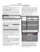
BEFORE OPERATING THE FURNACE CHECK BURNER ALIGNMENT WITH COMBUSTION CHAMBER. THE END CONE OF THE AIR TUBE MUST BE CENTRED TO THE ACCOMODATING RING PROVIDED IN THE DESIGN OF THE COMBUSTION CHAMBER. ADJUST AS NECESSARY. DO NOT START THE BURNER UNLESS THE BLOWER ACCESS DOOR IS SECURED IN PLACE. 19a. CIRCULATING AIR BLOWER (O4HD091A-12-FB) The O4HD-091A-12-FB, O4HD-091A-14-FA-DV and O4HD-091A-V-FA furnace models are equipped with direct drive blower systems.
20. MAINTENANCE AND SERVICE Routine Maintenance By Home Owner DO NOT CONNECT POWER LEADS BETWEEN MOTOR SPEEDS. THE NEUTRAL WIRE MUST ALWAYS BE CONNECTED TO THE MOTOR'S DESIGNATED NEUTRAL TERMINAL. If the joining of the blower speed wiring is done in the furnace junction box, tape off both ends of the unused wire.
The venting system should be cleaned and inspected for signs of deterioration. Replace pitted or perforated vent pipe and fittings. The barometric damper should open and close freely. test is complete, shut off electrical power to the furnace, replace the neutral wire to the blower fan motor, and then restore power. The blower fan will start up immediately. Once the temperature has dropped and the limit control has reset, the fan will operate until the fan off time is achieved.
22. ECM BLOWER MOTOR OPERATION (O4HD-091A-V-FA) temperature has dropped and the limit control has reset, the fan will operate until the fan off time is achieved. The oil burner will then resume operation and continue until the thermostat is satisfied. Restore the thermostat setting to a comfortable temperature. Setting Blower “ON” and “OFF” Timings Blower on/off time delays are handled by ECM motor programming.
Appendix A- O4HD-091A-12-FB, O4HD-091A-14-FA-DV AND O4HD-091A-V-FA O4HD-091A-12-FB, O4HD-091A-14-FA-DV and O4HD-091A-V-FA furnaces may be used with the following oil burners. Please note: The Beckett AF oil burner is for applications using indoor air for combustion only. For sidewall venting applications utilizing outdoor air for combustion, use the Beckett AFII (Balanced Flue) oil burner only.
NOTE: Air gate setting may vary for sidewall vented units where air gate must be adjusted to achieve zero smoke. A.1 OIL BURNER AIR ADJUSTMENT A.3 START UP For complete details, consult the oil burner instruction manual provided in the furnace documents envelope. The furnace should be operated for a minimum of 10 minutes to reach steady state conditions before fine tuning combustion. The warm up time is ideal for testing the oil pump pressure.
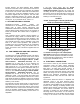
Table A-6 Direct Drive Blower Set-Up PSC Motor Blower Set-Up 0.20 in. w.c. Cooling Capacity 0.50 in. w.c.
Table A-8 Direct Drive Blower Characteristics ECM Motor CFM RANGE Furnace Model O4HD-070A-V-FA O4HD-091A-V-FA O4HD-105A-V-FA Blower 100-10 DD Motor HP Motor FLA ∆T 1/2 HP ECM 7.7 60°F 14 Continuous Heating Cooling Fan 0.28 - 0.48 inches w.c. 0.5 inches w.c.
Table A-9 General Dimensions (Inches) Cabinet Plenum Openings Return Furnace Model Width Depth Height Supply Side Bottom Flue Diameter 22 30 -3/4 49-5/8 20½ x 20 14 x 22 14 x 22 5 (LB.
Table A-10 ECM Blower Set-Up (O4HD-091A-V-FA) DIP SWITCH ADJUSTMENT CHART FOR INPUT 0.50 USGPH TO 0.75 USGPH SW1 - HEAT DIP Switch Position 1 2 OFF OFF ON OFF OFF ON ON ON SW3 - ADJUST DIP Switch Position 1 2 OFF OFF ON OFF OFF ON ON ON SW2 - COOL POS. A B C D INPUT USGPH 0.65 N/A 0.75 0.50 DIP Switch Position 1 2 OFF OFF ON OFF OFF ON ON ON POS. A B C D AC Size (TON) 3 2.5 2 1.5 SW4 - DELAY POS. A B C D CFM 0% (+)15% (-)15% N/A DIP Switch Position 1 2 OFF OFF ON OFF OFF ON ON ON POS.
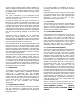
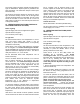
Chimney Vent Burner Wiring Diagram O4HD-091A-12-FB O4HD-091A-V- APPENDIX B: WIRING DIAGRAMS LEGEND/legende 120 V 24 V FACTORY WIRING filage a l'usine 120 V 24 V FIELD WIRING filage au champs INDOOR BLOWER ventilateur principale MOTOR moteur L C ML H MHI L1 530SE BL COM 24V BK YL WH CAP BL V VALVE/ soupappe 3 4 5 N EAC 2 6 HUM 2 COOL 1 1 HEAT 3 7 VI C YL GR 3 3 WH 4 WH AL 1008 11 BR BL 3 1 2 4 1 3T (T1) 2 BURNER MOLEX CONNECTOR/ connecteur molex du brûleur 1 2
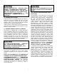
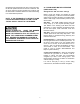
Direct Vent Burner Wiring Diagram O4HD-091A-14-FA-DV LEGEND/legende 120 V 24 V FACTORY WIRING filage a l'usine 120 V 24 V FIELD WIRING filage au champs 3 INDOOR BLOWER ventilateur principale BR BR MOTOR moteur L C ML H MHI GROUND/Terre TERMINAL PROVIDED/ point de raccord fourni BK WH 120V 1 2 3 24V COM 24V VI YL BL F C V NC OR BR BK WH WH CAP 3 4 5 N 2 6 VI X HUM 2 COOL 1 1 HEAT 3 EAC VALVE/ soupappe YL BURNER V VI 7 C RD RD 3 11 WH 12 RD WH 4 2 1 4 2
OPERATION OF OIL BURNER Once the furnace flue pipe, electrical and oil line connections have been made, use the following instructions to set the burner: Shut off the electrical power to the furnace. Install an oil pressure gauge to the pressure port on the oil pump. (Refer to the oil pump specification sheet included with the burner instructions). Restore electrical power to the furnace. Start the furnace and bleed all air from the fuel oil lines. the heat anticipator.
APPENDIX C OIL PRIMARY CONTROL DETAILED SEQUENCE OF OPERATION Power is applied to unit. The oil primary control completes a self-diagnostic procedure. If no light or flame is present, and unit passes its self-diagnostic procedure, the control enters into the idle mode. Thermostat calls for heat: A) Safety check is made for flame (4 second delay). 1) If flame is not present, the oil primary control will apply power to the burner motor and igniter.
FIGURE 4: UNITED TECHNOLOGIES 1158-120 FAN TIMER BOARD (O4HD-091A-12-FB and O4HD-091A-14-FA-DV) FIGURE 5: UNITED TECHNOLOGIES 1168-1 ECM TAP BOARD (O4HD-091A-V-FA) 21
IDLE STATE THERMOSTAT CALLS FOR HEAT SAFETY CHECK FOR FLAME (5 SEC.) OIL PRIMARY CONTROL SEQUENCE of OPERATION REMAINS IN IDLE STATE NO FLAME FLAME BURNER MOTOR & IGNITOR START 10 SEC. SAFETY CHECK FOR FLAME (5 SEC.
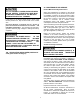
Table C-1: 1158-120 ELECTRONIC FAN TIMER BOARD (EFT) DETAILED SEQUENCE OF OPERATION Mode Action Thermostat calls for heat. ("W" terminal is energized). HEAT Thermostat ends call for heat. ("W" terminal is de-energized). Burner fails to light. Established flame fails. COOL FAN Thermostat begins call for cool. (G and Y terminals are energized). Thermostat ends call for cool. (G and Y terminals are deenergized). Thermostat begins call for fan. (G terminal is energized). Thermostat ends call for fan.
TROUBLESHOOTING OIL PRIMARY CONTROL LED DIAGNOSTIC LIGHT IMPORTANT: Due to the potential hazard of line voltage, only a trained, experienced service technician should perform the troubleshooting procedure. The LED diagnostic light has several functions. It indicates the state or mode in which the oil burner is operating. It will also indicate fault conditions, and help determine cad cell resistance while the burner is operating.
PRELIMINARY CHECKS: Make sure that limit switches are closed and those contacts are clean. ELECTRICAL SHOCK HAZARD. Check for line voltage power on the oil primary control black and white lead wires. TROUBLESHOOTING IS DONE WITH THE SYSTEM POWERED. BE CAREFUL TO OBSERVE ALL NECESSARY PRECAUTIONS TO PREVENT ELECTRICAL SHOCK OR EQUIPMENT DAMAGE. Refer to Table C-4 or C-5 for further troubleshooting information.
Table C-3: Oil Primary Control Troubleshooting continued from previous page Procedure 4. Shield cad cell from external light. 5. Jumper thermostat (T -T) terminals on oil primary control IMPORTANT First remove one thermostat lead wire. Status Indicator light turns off. Corrective Action Eliminate external light source or permanently shield cad cell. Replace cad cell with new cad cell and recheck. If indicator light does not turn off, remove cad cell lead wires from oil primary control and recheck.
Table C-3: Oil Primary Control Troubleshooting continued. Procedure Status Corrective Action Indicator light is on. Remount control onto burner housing. Go to step 6. 10. Check cad cell. Disconnect line voltage power and open line switch. Remove existing cad cell and replace with new cad cell. Disconnect all wires from thermostat terminals to ensure Indicator light is off. Go to step 11. that there is no call for heat. Reconnect line voltage power and close line switch.
Table C-4: System and General Troubleshooting continued Problem Furnace will not start. Possible Cause Photo Cell wiring shorted or room light leaking into photo cell compartment Open safety switch. No fuel oil. Clogged nozzle. Furnace will not start without first pushing oil primary control reset button. (Happens on frequent basis) Clogged oil filter. Low oil pump pressure. Air getting into fuel oil lines, or fuel oil line dirty, clogged, or in some manner defective. Defective burner motor.
Table C-4: System and General Troubleshooting continued Problem Possible Cause System temperature rise too high. Poor “fan off” delay timing selection, (fan stops too soon). Excessive fuel oil consumption. Fuel oil leak. Check fuel oil line for leaks. Repair or replace if necessary. Stack temperature too high. Check stack temperature. Stack temperatures will normally range from 350° to 450°F. Check draft regulator. Draft should be set to -0.02 in. w.c.
Table C-4: System and General Troubleshooting continued Problem Supply air temperature too hot. Supply air temperature too cool. Supply air temperature too cool during first moments of furnace cycle. Possible Cause Airflow blocked or dirty air filter. Insufficient airflow. Excess airflow. Excessive duct losses. Fan control "fan on" setting too low. Excessive duct losses. Remedy Clean or replace air filter. Check all dampers. Open closed dampers including registers in unused rooms.
HOMEOWNER’S REFERENCE TABLE Model No. Serial No. Date Installed Contractor Contact Address Postal Code Telephone No. After Hours No. FUEL SUPPLIER Fuel Oil Supplier Contact Telephone No. After Hours No. IF DIFFERENT FROM INSTALLATION CONTRACTOR: Service Tech. Telephone No. After Hours No.
PARTS LISTING: HIGHBOY MODEL: O4HD-091A-12-FB & O4HD-091A-V-FA Ref. No.
PARTS LISTING: HIGHBOY MODEL: O4HD-091A-12-FB O4HD-091A-V-FA Ref. No. Description Part No.
NOTES: NORDYNE, 8000 Phoenix Parkway, O’Fallon, Missouri, 63368 35 151B-0810 (Replaces 151B-0909)