
Manual


AQUASMART
TM
2-IN-1 SENSOR (Temperature & Presence of Water)
Installation Instructions
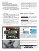
PARTS:
For proper operation, there must be
a secure electrical bond between
the green sensor wire from the sensor and the boiler
metal vessel in direct contact with the boiler water.
Failure to secure an electrical bond will result in the
AquaSmart locking out and displaying, “LOCKOUT
- LOW WATER”.
Explosion,
Burn and Scald Hazards
Excessive water temperatures could cause explosion,
burns, scalding, pressure relief fl ooding and fi tting leaks.
The 2-in-1 Sensor shall only be installed by a trained
professional.
The sensor must be installed in the proper location for
correct low water cut-off (LWCO) operation in
accordance with the Boiler Manufacturer’s instructions.
The 2-in-1 sensor body is installed directly into the
boiler wall tapped hole in place of an immersion well.
Carefully follow the outlined procedures for temperature
sensor installation to ensure accurate water temperature
sensing and effective control operation.
Make sure the plumbing for domestic hot water has anti-
scald valve protection.
Follow all applicable safety codes, rules and guidelines
for installing an immersion well. Improper installation can
result in the Boiler overheating.
y
y
y
y
y
y
Do not use in steam applications. For use in hot water boilers or water
heaters only. Do not use outside of the intended use and specifi cations.
Technical Specifi cations
Storage Temp. Range:
Operating Temp. Range:
Maximum Pressure:
Installation(screw-in)Torque Range:
-40°F to 250°F
32°F to 250°F
250 PSIG
185-200 in/lbs
Leak, Burn, and Scald
Hazards
Incompatible thread sealants could severely damage
the sensor threads.
Only use Tefl on
®
Tape or Rectroseal
®
No. 5
®
(soft-set).
DO NOT use any anaerobic fast-setting sealants such
as, but not limited to, Loctite
®
, Leak Lock
®
,
Permatex
®
, or Gasoila
®
.
Call RWB Technical Services at 1(800)645-2876 to
confi rm, if unsure.
y
y
y
Installation Instructions on back.
(1) 76002N1SXX 2-IN-1 Sensor
(1) 32704 Pipe Clamp for sensor ground
(1) 3214771 36” Green Ground Wire
Part # Lead Length
Insulation Depth
(A)
Insertion Depth
(B)
76002N1S01 8-1/4” 1-1/2” 1-5/8”
76002N1S02 6-1/4” 3-1/2” 1-5/8”
76002N1S05 5.0” 4-3/4” 1-5/8”
76002N1S06 8-1/4” 1-1/2” 7/8”