CF Oil Burner Instruction Manual ON/OFF Operation Firing rate: CF500: 1.75 – 5.50 GPH CF800: 3.00 – 8.00 GPH Motor voltage: 120 / 60 Hz std. Thank you for purchasing a Beckett burner. With proper care and regular maintenance, it will provide years of trouble-free service. Please take a few minutes to read the section entitled “To the owner” inside this manual. Then, keep the manual in a safe place where it can be easily located if needed by your professional service technician.
Instruction Manual – Model CF500/CF800 Oil Burner Please . . . read this page first Hazard definitions The following will be used throughout this manual to bring attention to hazards and their risk factors, or to special information. Denotes presence of a hazard which, if ignored, will result in severe personal injury, death or substantial property damage. Denotes presence of a hazard which, if ignored, could result in severe personal injury, death or substantial property damage.
Instruction Manual – Model CF500/CF800 Oil Burner Warranty Contents Beckett warrants its equipment to those who have purchased it for resale, including your dealer. If you have any problems with your equipment or its installation, you should contact your dealer for assistance. Please . . . read this page first ................ 2 Pre-installation checklist........................... 4 Refer to warranty sheet in literature packet included with burner for details. Mount the burner .......................
Instruction Manual – Model CF500/CF800 Oil Burner Pre-installation checklist ❏ Combustion air supply ❏ Vent system • The burner requires combustion air and ventilation air for reliable operation. Assure that the building and/or combustion air openings comply with National Fire Protection Standard for Oil-Burning Equipment, NFPA 31.
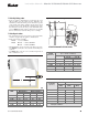
Instruction Manual – Model CF500/CF800 Oil Burner ❏ Verify firing rate Figure 2 - Air tube mounting dimensions • Refer to appliance manufacturer’s instructions (if available) for firing rate and nozzle selection. Otherwise, the maximum recommended firing rate for the burner depends on the length of the firing chamber and the distance from the burner center to the chamber floor. Verify that the chamber dimensions are at least as large as the minimum values given in Figure 1.
Instruction Manual – Model CF500/CF800 Oil Burner Mount the burner ❏ Mount flange(s) on air tube Figure 3 - Mount flange(s) on air tube • This section does not apply to burners with welded flanges. • Do not install air tube on burner. • For non-pressure firing flange, refer to Figure 3: Install gasket (item a ) and flange (item d ). Ignore the next paragraph. • For pressure-firing flange, refer to Figure 3: Slide gasket (item a) onto the air tube, making sure the top of the air tube is up.
Instruction Manual – Model CF500/CF800 Oil Burner ❏ Install nozzle line assembly Figure 5 - Nozzle line assembly in burner • Insert the nozzle line assembly into the burner air tube. • Slide the secondary adjusting plate (Figure 6, item f) completely to the left on the indicator adjusting plate (item e). Finger-tighten acorn nut c to secure the two plates together. Slide both plates completely to the right (Indicator plate will read 0). Tighten fastener d.
Instruction Manual – Model CF500/CF800 Oil Burner Connect fuel line(s) Install the oil lines using the following guidelines. Failure to comply could lead to equipment damage and present a risk of severe personal injury, death or substantial property damage due to leakage of oil and potential fire hazard. Use only flare fittings at joints and connections. Never use compression fittings. Install fittings only in accessible locations to assure any leak will be detected.
Instruction Manual – Model CF500/CF800 Oil Burner ❏ Burner fuel flow Figure 7 – One-pipe oil flow with “B” pump • One-pipe systems – See Figure 7 for the fuel flow path. • Oil supply connects to one of the fuel unit inlet ports. • Two-pipe systems – See Figure 8 for the fuel flow paths for two-pipe oil systems. • Oil supply connects to one of the fuel unit inlet ports. Oil return connects to the fuel unit return port. (Install the by-pass plug in the fuel unit for two-pipe systems.
Instruction Manual – Model CF500/CF800 Oil Burner Wire the burner — R7184 Install the burner and all wiring in accordance with the National Electrical Code and all applicable local codes or requirements. Wire the burner in compliance with all instructions provided by the appliance manufacturer. Verify operation of all controls in accordance with the appliance manufacturer's guidelines. See Figure 9a for a typical wiring diagram, with R7184 oil primary, for reference purposes only.
Instruction Manual – Model CF500/CF800 Oil Burner Wire the burner — R8184 (alternate) Install the burner and all wiring in accordance with the National Electrical Code and all applicable local codes or requirements. Do not by-pass any safety control. By-passing a safety control could result in severe personal injury, death or substantial property damage. Wire the burner in compliance with all instructions provided by the appliance manufacturer.
Instruction Manual – Model CF500/CF800 Oil Burner Prepare the burner for start-up Start-up checklist – Verify the following before attempting to start burner. ❏ Combustion air supply and venting have been inspected and verified to be free of obstructions and installed in accordance with all applicable codes. ❏ Oil nozzle has been selected correctly and securely installed in the nozzle adapter. ❏ Fuel unit by-pass plug has not been installed for one-pipe oil system.
Instruction Manual – Model CF500/CF800 Oil Burner Start the burner Do not proceed unless all prior steps in this manual have been completed. Failure to comply could result in severe personal injury, death or substantial property damage. Do not attempt to start the burner when excess oil has accumulated, when the appliance is full of vapor or when the combustion chamber is very hot.
Instruction Manual – Model CF500/CF800 Oil Burner Start the burner continued ❏ Set air adjusting plate 1. Allow the burner to run until the appliance has warmed sufficiently. b. Increase the air to reduce CO2 by 2 percentage points at a zero smoke level. (Increase O2 by 3 percentage points at a zero smoke level.) Example: Reduce CO2 from 13.5% to 11.5%, with zero smoke (or increase O2 from 2.5% to 5.5%). 2. Visually check the flame. The flame should not be dark orange or smoky.
Instruction Manual – Model CF500/CF800 Oil Burner Replacement parts Item 1 2 3 4 5 6 Part name Air tube Flange kit Electrode assembly Air shutter Nozzle line assembly Head assembly 7 8 10 11 12 17 20 21 Fuel lines Air band Adjusting plate assembly Spline nut Fuel pump Coupling Control Ignitor -22 23 Transformer Motor Blower wheel 24 Pedestal kits Description Refer to Figure 2, page 5 Refer to Figure 10, below Part number Specify 3215 Refer to Figure 2, page 5 CF500 — KK CF800 — KH (Tube A) CF800
Instruction Manual – Model CF500/CF800 Oil Burner U.S.A.: P. O. Box 1289 • Elyria, Ohio 44036 • 800-645-2876 • 440-327-1060 • FAX 440-327-1064 Canada: R. W. Beckett Canada, Ltd.