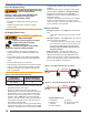
COMMERCIAL PRODUCTS Potential for Fire, Smoke and Asphyxiation Hazards Incorrect installation, adjustment, or misuse of this burner could result in death, severe personal injury, or substantial property damage. To the Homeowner or Equipment Owner: y Please read and carefully follow all instructions provided in this manual regarding your responsibilities in caring for your heating equipment. y Contact a professional, qualified service agency for installation, start-up or service work.
To the Owner: Thank you for purchasing a Beckett burner for use with your heating appliance. Please pay attention to the Safety Warnings contained within this instruction manual. Keep this manual for your records and provide it to your qualified service agency for use in professionally setting up and maintaining your oil burner. Your Beckett burner will provide years of efficient operation if it is professionally installed and maintained by a qualified service technician.
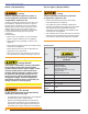
Section: General Information General Information Hazard Definitions Indicates a hazardous situation, which, if not avoided, will result in death or serious injury. Indicates a hazardous situation, which, if not avoided, could result in death or serious injury. Owner’s Responsibility Incorrect installation, adjustment, and use of this burner could result in severe personal injury, death, or substantial property damage from fire, carbon monoxide poisoning, soot or explosion.
Section: General Information Owner’s Responsibility: Service Agency Responsibility: Follow these instructions exactly. Failure to follow these instructions, misuse, or incorrect adjustment of the burner could result in asphyxiation, explosion or fire. Follow these instructions exactly. Failure to follow these instructions could result in asphyxiation, explosion or fire. Contact a professional, qualifi ed service agency for the installation, adjustment and service of your oil burning system.
Section: Pre-installation Checklist Pre-installation Checklist ○ Combustion Air Supply Adequate Combustion and Ventilation Air Supply Required Failure to provide adequate air supply could result in asphyxiation, explosion or fire hazards. If fuel supply is level with or higher than fuel unit ○ y The burner cannot properly burn the fuel if it is not supplied with a reliable combustion air source.
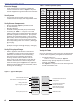
Section: Pre-installation Checklist Table 1 - Nozzle Capacities (GPH) Electrical Supply ○ Verify that the power connections available are correct for the burner. Refer to Figure 1. All power must be supplied through fused disconnect switches. Rated gph @ 100 psig Pressure - pounds per square inch 125 150 175 200 250 275 300 Vent System 2.00 2.24 2.45 2.65 2.83 3.16 3.32 3.46 ○ 2.25 2.52 2.76 2.98 3.18 3.56 3.73 3.90 2.50 2.80 3.06 3.31 3.54 3.95 4.15 4.33 2.75 3.07 3.
Section: Pre-installation Checklist Figure 2 - Dimensions: Minimum Combustion Figure 3 - Firebox Pressure: CF1000 with no Reserve Air Chamber and Air Tube Mounting. 15 * Install burner with 2° pitch as shown. D Maximum Firing Rate U.S. GPH T 1/4” ± 1/8” H 14 *2° L E 13 12 KD 11 10 9 0.0 (refractory-lined) 0.4 0.6 0.8 1.0 Firebox Pressure in Inches Water Column (W.C.) Minimum Dimensions Firing Rate 0.2 (wet-base boilers) H L H L 0 to 5 gph 7.0” 25.0” 7.0” 25.
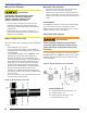
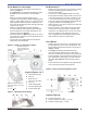
Section: Mount the Burner Mount the Burner Mount Air Tube to Burner ○ Protect the air tube from overheating. Overheating could cause damage to the air tube and other combustion components leading to equipment malfunction and impaired combustion performance. y The end of the air tube must not extend into the combustion chamber unprotected unless it has been factory-tested and specified by the appliance manufacturer.
Section: Mount the Burner Install Nozzle Line Assembly Set Dimension Z ○ ○ ○ ○ ○ ○ ○ Insert the nozzle line assembly into the burner air tube as in Figure 6. See Figures 6 and 7. Assemble the adjusting plate assembly per the instructions in the assembly packet. Slide the secondary adjusting plate (item f) completely to the left on the indicator adjusting plate (item e). Finger tighten acorn nut c to secure the two plates together.
Section: Mount the Burner Fuel Unit By-pass Plug Do Not Install By-pass Plug with 1-Pipe System Failure to comply could cause immediate pump seal failure, pressurized oil leakage and the potential for a fi re and injury hazard. ○ ○ y The burner is shipped without the by-pass plug installed. y Install the by-pass plug in two-pipe oil supply systems ONLY. This will reduce vibration and noise transmission problems.
Section: Burner Controls Burner Controls Typical Burner Sequence of Operation GeniSys 7505 Refer to the appliance manufacturer’s wiring diagram for actual specifications. 1. Standby: The burner is idle, waiting for a call for heat. 2. Valve-On Delay: The igniter and motor are on while the control delays turning on the oil solenoid valve for the programmed time. 3. Trial For Ignition: The oil solenoid valve is energized.
Section: Burner Controls Wire the Burner (GeniSys 7505) Electrical Shock Hazard Electrical shock can cause severe personal injury or death. Install the burner and all wiring in accordance with the National Electrical Code and all applicable local codes or requirements. y Disconnect electrical power before installing or servicing the burner. Wire the burner in compliance with all instructions provided by the appliance manufacturer.
Section: Burner Controls Figure 13 - Typical Wiring (7505P) CF1000 Burner Manual 13
Section: Burner Controls to check the cad cell resistance range. The yellow light will flash 1 to 4 times, depending on the amount of light detected by the cad cell. Typical Burner Sequence of Operation Honeywell 7184 1. Standby — The burner is idle, waiting for a call for heat. When a call for heat is initiated, there is a 3-10 second delay while the control performs a safe start check.
Section: Burner Controls Figure 15 - Typical Wiring (R7184) CF1000 Burner Manual 15
Section: Prepare the Burner for Start-up Prepare the Burner for Start-up Professional Installation and Service Required Incorrect installation and mishandling of startup could lead to equipment malfunction and result in asphyxiation, explosion or fire. y This burner must be installed and prepared for startup by a qualified service technician who is trained and experienced in commercial oil burner system installation and operation. y Do not attempt to start the burner unless you are fully qualified.
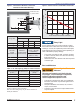
Section: Prepare the Burner for Start-up Z Dimension Initial Head Position Should be set according to the instructions given previously in this manual. The top acorn nut (Figure 16, item d) should never be loosened once the Z dimension is initially set. (See Figure 16) Figure 16 - Adjusting Plate Initial Setting, Typical ○ ○ ○ The indicator plate assembly (item e) markings correspond to head position settings.
Section: Start the Burner Set Appliance Limit Controls ○ Set the appliance limit controls in accordance with the appliance manufacturer’s recommendations. Prepare the Fuel Unit for Air Venting ○ ○ To vent air from one-pipe oil systems, attach a clear hose to the pump air bleed valve (Figure 9) on the fuel unit. Provide a container to catch the oil. Loosen the pump air bleed valve. Vent the air as described under Starting the Burner and Venting Air.
Section: Start the Burner Priming the Pump 1. Verify that the air adjusting cam (Figure 16, item L) has been set to the initial low-fi re air setting as described under the ‘Initial Air Settings’ section. 2. Open the oil shutoff valves in the oil supply line to the burner. 3. Set the thermostat (or operating control) to call for heat. 4. Close the line switch to the burner. The burner motor should start immediately. 5.
Section: Start the Burner Set Air Adjusting Plate Figure 17 - Air Damper Assembly See (Figure 17) 1. Allow the burner to run until the appliance has warmed sufficiently. 2. Visually check the flame. The flame should not be dark orange or smoky. If the flame appears to be smoking, increase the amount of air by re-adjusting the damper indicator to a higher number. H 3. Once the appliance has warmed, the air setting can be checked and adjusted. 4. Use combustion test instruments to adjust the burner. a.
Section: Maintenance and Service Maintenance and Service □ Clean the blower wheel, air inlet, air guide, and burner housing of any lint or foreign material. □ If motor is not permanently lubricated, oil motor with a few drops of SAE 20 non detergent oil at each oil hole. DO NOT over oil motor. Excessive oiling can cause motor failure. Annual Professional Service Required Tampering with or making incorrect adjustments could lead to equipment malfunction and result in asphyxiation, explosion or fire.
Replacement Parts for best performance specify genuine Item Beckett replacement parts Part Name Description Part Number 1 Oil Valve Mounted on Junction Box 21789U 2 Knurled Nut All Models 3666 3 Adjusting Plate Assembly CF10-2300 Kit 51213U 4 Fuel Pump B2TA-8245 21313U 5 Damper Spring All models 4339 6 Air Proving Switch 2” W.C.
Figure 19 - Replacement Parts 1 6 7 2 3 4 8 5 10 9 15 11 14 18 SK9936 13 12 17 16 19 21 CF1000 Burner Manual 22 20 23 23
Limited Warranty Information The R. W. BECKETT CORPORATION (“Beckett”) warrants to persons who purchase its “Products” from Beckett for resale, or for incorporation into a product for resale (“Customers”), that its equipment is free from defects in material and workmanship. To qualify for warranty benefits, products must be installed by a qualified service agency in full compliance with all codes and authorities having jurisdiction, and used within the tolerances of Beckett’s defined product specifications.