! WARNING Potential for Fire, Smoke and Asphyxiation Hazards Incorrect installation, adjustment, or misuse of this burner could result in death, severe personal injury, or substantial property damage. To the Homeowner or Equipment Owner: y Please read and carefully follow all instructions To the Professional, Qualified Installer or Service Agency: y Please read and carefully follow all instructions provided provided in this manual regarding your responsibilities in caring for your heating equipment.
Form 6104 BCF10-R06
Before you begin . . . The following resources will give you addional information for your installation. We suggest that you consult these resources whenever possible. Pay particular attention to the appliance manufacturer’s instructions. Appliance manufacturer’s instructions -Always follow the appliance manufacturer’s instructions for burner installation, equipment and set-up. 1–800–OIL–BURN - Beckett’s technical services hot-line. www.beckettcorp.com - Beckett’s website.
To the Owner: Thank you for purchasing a Beckett burner for use with your heating appliance. Please pay attention to the Safety Warnings contained within this instruction manual. Keep this manual for your records and provide it to your qualified service agency for use in professionally setting up and maintaining your oil burner. Your Beckett burner will provide years of efficient operation if it is professionally installed and maintained by a qualified service technician.
Owner’s Responsibility: Follow These Instructions Exactly Failure to follow these instructions, misuse, or incorrect adjustment of the burner could lead to equipment malfunction and result in asphyxiation, explosion or fire. Contact a professional, qualified service agency for the installation, adjustment and service of your oil burning system. Thereafter, have your equipment adjusted and inspected at least annually to ensure reliable operation.
Combustion air supply y The burner requires combustion air and ventilation air for Nozzle pressure reliable operation. Assure that the building and/or combustion air openings comply with National Fire Protection Standard for Oil-Burning Equipment, NFPA 31. For appliance/burner units in confined spaces, the room must have an air opening near the top of the room plus one near the floor, each with a free area at least one square inch per 1,000 Btu/hr input of all fuel burning equipment in the room.
y The fuel unit nozzle port pressure is factory set at 300 psig. Some original equipment manufacturer burner applications may call for a lower pressure to obtain a required firing rate. Do not change this pressure unless directed to do so by the appliance manufacturer. Figure 1. Min. Combustion Chamber Dimensions Vent system y The flue gas venting system must be in good condition and must comply with all applicable codes.
Mount the burner Mount air tube to burner y Remove the rear access door from the back of the burner for improved access to the interior. Protect the Air Tube From Overheating Overheating could cause damage to the air tube and other combustion components leading to equipment malfunction and impaired combustion performance. y The end of the air tube must not extend into the comy bustion chamber unprotected unless it has been factorytested and specified by the appliance manufacturer.
Figure 4 - Nozzle and nozzle line assembly Install nozzle line assembly y Insert the nozzle line assembly into the burner air tube as in Figure 5. y See Figures 5 and 6. Assemble the adjusting plate assembly per the instructions in the assembly packet. y Slide the secondary adjusting plate (item f) completely to y y y the left on the indicator adjusting plate (item e). Finger tighten acorn nut c to secure the two plates together.
Insert burner y Position the burner in the front of the appliance and loosely Oil supply/return lines tighten the nuts on the mounting studs. The burner should be pitched downward 2° as shown in Figures 2 and 3. y Install the oil tank and oil lines in accordance with all y See Figure 7. Install the pedestal support kit (recommend- y Size the oil supply and return lines using the guidelines ed) by attaching the ¾” NPT flange (item a) to the bottom of the burner using the (4) #10 screws provided.
Table 3 - Fuel unit gearset capacities Fuel unit model number Gearset capacity (gallons per hour) B2TA8245 21 Figure 8 - One-pipe oil flow with “B” pump 300 psig 300 psig Burner fuel flow Install Oil Supply To Specifications Failure to properly install the oil supply system could cause oil leakage, equipment malfunction, puff-back of hot gases, heavy smoke, asphyxiation, explosion and fire hazards.
Wire the burner — R7184 Electrical Shock Hazard Professional Installation and Service Required Incorrect installation and mishandling of start-up could lead to equipment malfunction and result in asphyxiation, explosion or fire. y This burner must be installed and prepared for start-up Electrical shock can cause severe personal injury or death. by a qualified service technician who is trained and experienced in commercial oil burner system installation and operation.
Sequence of Operation Prepare the burner for (typical) start-up 1 Start-up checklist - Verify the following before attempting to start burner. Combustion air supply and venting have been inspected 1. Standby — The burner is idle, waiting for a call for heat. When a call for heat is initiated, there is a 3-10 second delay while the control performs a safe start check. 2. Valve-on delay — As applicable, the ignition and motor are turned on for a 15-second prepurge. 3.
Adjusting plate assembly (Figure 11) Figure 12 - Air damper assembly Make sure spline nut (item b) and bottom acorn nut (item c) are loose. Initial head position (Figure 11) y The indicator plate assembly (item e) markings correspond y y to head position settings. Slide the secondary adjusting plate (item f) toward the rear of the burner until the number on the indicator plate corresponds to the initial head setting given in Table 4 for the desired firing rate.
Set appliance limit controls Start the Burner y Set the appliance limit controls in accordance with the Explosion and Fire Hazard appliance manufacturer’s recommendations. Failure to follow these instructions could lead to equipment malfunction and result in heavy smoke emission, soot-up, hot gas puff-back, fire and asphyxiation hazards. Prepare the fuel unit for air venting y To vent air from one-pipe oil systems, attach a clear hose to y the vent plug on the fuel unit.
5. If the burner motor does not start, reset the motor overload switch (if so equipped) and press the reset switch of the burner primary control. 6. Vent the fuel unit as soon as the burner motor starts rotating. To vent — Attach a clear plastic tube to the air bleed valve (Figure 8 or 9 as applies, item p). Place the end of the tube in a container to catch the oil. Then loosen the fuel unit air vent valve. Tighten the air vent valve after all air has been purged.
Maintenance and Service Annual Professional Service Required Tampering with or making incorrect adjustments could lead to equipment malfunction and result in asphyxiation, explosion or fire. y Do not tamper with the burner or controls or make y y y any adjustments unless you are a trained and qualified service technician. To ensure continued reliable operation, a qualified service technician must service this burner annually.
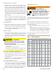
Replacement parts Item Part Name Description Part Number 1 Timer Nozzle valve delay 21295U 2 Oil Valve Box mounted 21789U 3 Adjusting plate assembly CF10-2300 Kit 51213U 4 Knurled nut All models 3666 5 Fuel pump B2TA-8245 H3PAN-C150H 21313U 21309U 6 Pedestal kit All models 51193 7 Fuel lines Specify length - 8 Damper spring All models 4339 9 Sight glass All models 31346 10 Rear cover door assembly Cast aluminum door* Stamped sheet-metal door* 5994U 5201301U 11 Co
1 2 3 9 10 11 4 13 8 7 5 6 12 16 15 14 Figure 13 --Adjustable AdjustablemountMountFigure 14 ing ing Plates plates for for CF1000 CF1000 17 18 19 20 21 22 Form 6104 BCF10-R06 19
Limited Warranty Information Limited WARRANTY For Residential, Commercial and Specialty Burners The R. W.