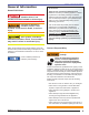
COMMERCIAL PRODUCTS Fire, Explosion and Asphyxiation Hazards Failure to follow these instructions exactly could lead to fire or explosion and result in death, severe personal injury or property damage. 1. Do not store or use gasoline or other flammable vapors and liquids in the vicinity of this or any other appliance. 2. What to do if you smell gas: - Do not try to light any appliance. - Do not touch any electrical switch. - Do not use any phone in your building.
Contents General Information .................................................... 3 Hazard Definitions: ........................................................................ 3 Owner’s Responsibility: ................................................................. 3 Professional Installer’s Responsibility: .......................................... 4 Specifications ................................................................................ 4 Pre-installation Checklist .............................
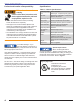
Section: General Information General Information Hazard Definitions: Indicates a hazardous situation which, if not avoided, will result in death or serious injury. Indicates a hazardous situation, which, if not avoided, could result in death, or serious injury. Used with the safety alert symbol, indicates a hazardous situation, which, if not avoided, may result in minor or moderate injury.
Section: General Information Professional Installer’s Responsibility: Follow these instructions exactly. Failure to follow these instructions could lead to equipment malfunction and result in asphyxiation, explosion or fire. Specifications Table 1 – Burner Specifications Input firing range 300 to 1200 MBh Fuel Natural gas - 0.6 specific gravity typical Gas train Standard: UL listed/CSD-1 Configuration Options: IRI and FM Manifold pressure 1.0 to 4.6 inches W.C.
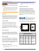
Section: Pre-installation Checklist Figure 1. Burner Nameplate General Model Information R.W. Beckett Construction and Setting Data Serial Number, Including Date Code R.W.
Section: Pre-installation Checklist ○ Test For Gas Pipe Leaks Leaking gas could result in asphyxiation, explosion, or fire hazard. y The gas supply piping must be absolutely leak-free. y Pressure test the gas piping with air that is at least three times greater than the gas pressure being used. y Verify that there are no leaks before proceeding. Clearances With the burner installed in the appliance, there must be adequate space in front of and on the sides of the burner to allow access and operation.
Section: Pre-installation Checklist Verify burner air tube assembly ○ ○ ○ Flames are shaped by their furnaces and by its flue locations. Increased height and width can decrease the length requirement. When shaping is too severe flames impinge on the walls. Impingement causes CO and carbon deposits and may damage the wall. Maintaining these minimum dimensions should prevent impingement, but smaller furnaces may be acceptable depending upon the results of applications testing.
Section: Pre-installation Checklist Figure 5. Burner Dimensions Burner Model Airtube Dim. A Dim. B O.D. 10.1 - 10.3, 10.1S - 10.3S 51927 25.0” 11.7” 4.43” 10.4 - 10.6 51928 26.0” 12.7” 4.86” 10.4S - 10.6S 51961 25.7” 12.5” 4.
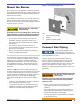
Section: Mount the Burner & Connect Gas Piping Mount the Burner Figure 6. Custom Mounting Plate Mount the burner to the appliance. The burner specified for packaged equipment will have a flange welded for the required insertion. Follow the appliance manufacturer’s instructions for mounting. In the absence of instructions, or for retrofits, make sure that the air tube insertion dimension, measured along the side of the air tube from the welded flange to the end of burner air tube, is correct.
Section: Connect Gas Piping Figure 7. Typical Gas Piping Layout ABBREV. HGPS LGPS MSC MLTC PG S SSOV1 TC U 2PRV LGPS METER ITEM DESCRIPTION HIGH GAS PRESSURE SWITCH LOW GAS PRESSURE SWITCH MAIN SHUTOFF COCK MAIN LEAK TEST COCK PRESSURE GAUGE STRAINER SAFETY SHUTOFF VALVE #1 TEST COCK UNION TWO POSITION REGULATING VALVE HGPS BURNER REGULATOR PG U DRIP LEG S MSC U SSOV1 TC 2PRV TC MLTC U TC (IF USED) FACILITY PIPING GAS UTILITY PIPING GAS TRAIN BURNER Table 1.
Section: Connect Gas Piping by natural gas appliances. It is safe and effective for propane usage in this design application. Optional – Gas trains for IRI and FM are available and must be specified when ordering a burner. Verify – Verify that the train components are not damaged and all piping and fittings are clean inside and out. The gas train is normally shipped as components and must be assembled and installed at the site.
Section: Wire the Burner Wire the Burner Install the burner and all wiring in accordance with the National Electric Code ANSI/NFPA 70 (Canada CSA C22.1) and all applicable codes and requirements. Wire the burner in compliance with all instructions and diagrams provided by the appliance manufacturer. Verify operation of all controls in accordance with the appliance manufacturer’s guidelines. See Figure 9 for a typical wiring diagram, with the RM7895A flame safeguard control, for reference purposes only.
Section: Sequence of Operation & Prepare the Burner for Start-up Sequence of Operation (Typical for RM7897A flame safeguard primary control) 1. Initiate – The primary control enters the INITIATE sequence when the control is first powered on or power returns after an interruption. The initiate sequence is a ten second delay during which the control verifies line voltage stability. 2.
Section: Prepare the Burner for Start-up Start-up checklist Verify the following before attempting to start the burner: 1. General ○ ○ ○ ○ Carefully read and become familiar with the CG10 Manual, Flame Safeguard Control Instructions, sequence of operation, pertinent wiring diagrams, gas system layout, insurance requirements, other controls and valve literature pertinent to the installation. Follow the appliance manufacturer’s start-up procedures (when available).
Section: Prepare the Burner for Start-up Figure 10.
Section: Start the Burner Start the Burner Professional Installation and Service Required Incorrect installation and mishandling of start-up could lead to equipment malfunction and result in asphyxiation, explosion or fire. y This burner must be installed and prepared for startup by a qualified service technician who is trained and experienced in commercial gas burner system installation and operation. y Do not attempt to start the burner unless you are fully qualified.
Section: Start the Burner Figure 11. Shutter and Band The shutter and band both control the amount of flow area available for air inlet to the burner. The greater their combined flow area, the higher the firing rate. The primary differences between the two are their ease of adjustment and their total airflow area. The shutter turns more easily and has a smaller net flow area.
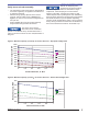
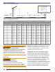
Section: Start the Burner Estimating Rate Manifold to Furnace Pressure information can be used to estimate the burner’s firing rate when it is not possible to clock a meter for the rate. To estimate the burner’s firing rate: Measure the furnace pressure over fire Measure the manifold pressure (at the manifold pressure test connection in Figure 10). Subtract the furnace pressure from the manifold pressure Compare the result to the data in Figure 12 or 13 as appropriate for your burner.
Section: Start the Burner Figure 12. Manifold to Furnace Pressure Drop vs. Rate - Stepped Spud Design 1400 Rate, MBH 1200 CG10.6S CG10.5S CG10.4S CG10.3S CG10.2S CG10.1S 1000 800 600 400 200 0 1 2 3 4 5 6 Pressure Drop, In. WC Figure 13. Manifold to Furnace Pressure Drop vs. Rate - Swirl Vane Head Design 900 800 Rate, MBH 700 600 CG10.3 CG10.2 CG10.1 500 400 300 200 100 0 1 2 3 4 5 Pressure Drop, In.
Section: Start the Burner Check operation and safety controls Testing by Qualified Technician Required. Failure to properly test and verify the correct function of operation and safety controls could lead to equipment malfunction and result in asphyxiation, explosion or fire. y The testing of operation and safety controls requires technical training and experience with commercial gas burning systems. y Carefully follow the manufacturer’s instructions supplied with the controls.
Section: Start the Burner Use test instruments to set combustion: Recommended combustion test sequence: Always use calibrated test instruments to set combustion levels. Verify that test instruments are calibrated and in good working condition. If not already provided, drill test access holes in the flue pipe near the breech (or upstream of the boiler breech damper, if applicable) and in the front mounting plate area for firebox pressure. Be careful not to damage any water-backed surface. 1.
Section: Maintenance and Service Maintenance and Service Annual Professional Service Required Tampering with or making incorrect adjustments could lead to equipment malfunction and result in asphyxiation, explosion or fire. y Do not tamper with the burner or controls or make any adjustments unless you are a trained and qualified service technician. y To ensure continued reliable operation, a qualified service technician must service this burner annually.
Section: Maintenance and Service 14. Inspect the condition of the appliance mounting plate and burner mounting flange gaskets and replace any damaged materials. See Figure 6. 15. Inspect all burner control wiring and the burner control panel for damaged insulation and loose terminals/connections. ○ Follow the guidelines under “Start the Burner” to set the combustion levels using test instruments. ○ Appliance – (Follow appliance manufacturer’s service procedures.
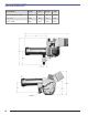
Section: Maintenance and Service Figure 14A – Gas Gun Assembly Figure 14B – Gas Gun Assembly Burner Head Adjustment - There is an optimum gas orifice size and burner head setting for each firing rate of the CG10 burner. The gas orifice size sets the gas flow velocity; the head setting establishes the airflow velocity. When those velocities are properly matched the burner provides its best performance and stability. The gas orifice size is built into the burner head.
Section: Maintenance and Service Propane Restrictor Description Installation The Beckett Propane Restrictor Conversion Kit allows for the conversion of CG10 burners for use with propane gas. With the proper installation of the restrictor and attached O-ring, adjustments and settings for propane use will be the same as the adjustments and settings for natural gas use as detailed in the burner manual. Note that Steps 1 and 2 on the following page refer to fully assembled burners.
Section: Maintenance and Service Use authorized replacement parts only. Restrictors are precisionmachined parts and O-rings are rated for fuel contact. Do not attempt to replicate or modify any parts. Refer to Table 3. Figure 17 – Gas Gun Assembly Installation The gun assembly is secured inside the air tube by a spring-loaded jacking screw. It is spring loaded in order to control the force it can impose on the gun assembly.
Section: Maintenance and Service For the OPERATOR Inspect Heating System Regularly Lack of regular inspections and inadequate maintenance could lead to equipment malfunction and result in asphyxiation, explosion or fire. (Always follow the appliance manufacturer’s recommended service instructions, when available.
Section: Replacement Parts Replacement Parts For best performance specify genuine 1 Beckett replacement parts. 3 2 7 6 4 5 17 16 15 14 17 13 12 17 11 19 10 8 Item 9 Description 18 20 Part # Item Description Part # Head Spec. Applic.
Section: Burner Configurations Burner Configurations The CG10 burner is offered in configurations that allow it to be customized to the capacity and furnace size needs of many different appliances. Two blower wheel sizes provide airflow capacity through the range. An air guide provides static pressure augmentation at low rates and an inlet sleeve maximizes flow capacity at high rates. Three air tube shrouds shape and stabilize the base of the flame.
Section: Burner Configurations The table below shows proven combinations of the components and the nominal firing rate ranges they serve. These combinations may vary and may be used outside of the nominal listed ranges based on results of specific applications tests conducted for OEM appliance manufacturers.
CG10 Burner Manual 31
Limited Warranty Information The R. W. BECKETT CORPORATION (“Beckett”) warrants to persons who purchase its “Products” from Beckett for resale, or for incorporation into a product for resale (“Customers”), that its equipment is free from defects in material and workmanship. To qualify for warranty benefits, products must be installed by a qualified service agency in full compliance with all codes and authorities having jurisdiction, and used within the tolerances of Beckett’s defined product specifications.