GeniSys 120V ™ PARTS & ACCESSORIES Model 7505 Advanced Burner Control Description / Applications The Beckett GeniSysTM Advanced Burner Control is a 120 Vac primary safety control for residential and light commercial oil burners used in boiler, furnace, and water heater applications having firing rates less than 20 GPH. The GeniSys is used with a suitable cad cell flame sensor to control the oil burner motor, igniter, and optional solenoid valve.
Features ◦ Thermostat / Operating (if applicable) and Limit Control Compatible ◦ Welded Relay Protection ◦ Limited Recycle ◦ Limited Reset ◦ 3 Status Lights ◦ Valve-On Delay / Motor-Off Delay (Field programmable with Beckett add-on Display) ◦ 15 Second Lockout Time ◦ Interrupted or Intermittent Duty Ignition ◦ Technician Pump Priming Mode ◦ Disable Function ◦ Communication Ports (2) Table 1 - Models and Cross Reference Guide Beckett GeniSys Control Part No.
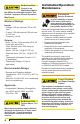
Figure 1 – Getting to know the control Reset Button with Red Light Yellow Light Green Light Communication Port 2 Thermostat Terminals (if applicable) Communication Port 1 Wiring Connections Cad Cell Connections Optional Snap-on Display Module: For programming and diagnostics Optional Snap-on Alarm Module: For adding isolated low voltage alarm contacts to the base control. See Alarm Module Instructions for specifications.
Do Not Use This Control in an Application that is Not Within the Ratings Listed in This Section. Improper Control Operation May Result. Electrical Ratings Inputs: ◦ Voltage: 120 Vac nominal (102 to 132 Vac) ◦ Current: 100 mA nominal (150 mA max at 132 Vac) ◦ Frequency: 60 Hz Outputs: ◦ Motor: 120 Vac, 10 full load amps (FLA), 60 locked rotor amps (LRA) *Note: Reduce motor FLA rating by igniter current ◦ Igniter: 120 Vac, 3 A @ 0.7 PF min ◦ Solenoid Valve: 120 Vac, 1 A @ 0.
Fire or Explosion Hazard Can cause severe injury, death, or property damage. • The control can malfunction if it gets wet, leading to accumulation of oil or explosive oil vapors. • Never install where water can flood, drip or condense on the control. • Never use a control that has been wet - replace it. Electrical Shock Hazard Electrical shock can cause severe personal injury or death. • Disconnect ALL electrical power to the appliance/burner circuit before installing or servicing this control.
Typical Boiler Wiring: Figure 2 – 7505A (for replacement of R8184G) Figure 4 – 7505B (for replacement of R7184B) ► Intermittent ignition, no valve-on delay, no motor-off delay ► Interrupted ignition, valve-on delay only (no motor-off delay) BOILER CONTROL BOILER CONTROL 70 T W T R 80 50 80 50 60 B2 B1 L1 L1 T W L2 L2 T R B2 B1 IGNITER 70 70 50 70 THERMOSTAT 60 60 50 80 L1 L2 80 60 L1 L2 THERMOSTAT IGNITER IGNITER IGNITER L2 (IGN) L2 (IGN) MOTOR L2 (MTR) MOTOR
Typical Furnace Wiring: Figure 6 – 7505A (for replacement of R8184G) Figure 8 – 7505B (for replacement of R7184B) ignition, no valve-on or motor-off delays 70 80 SAFETY AND OPERATING LIMITS 80 60 60 70 60 70 W L2 R 50 50 L1 W SAFETY AND OPERATING LIMITS ignition, valve-on delay only (no motor-off delay) 80 60 50 L1 L2 ► Interrupted 70 R 50 80 ► Intermittent THERMOSTAT THERMOSTAT IGNITER IGNITER IGNITER IGNITER L2 (IGN) L2 (IGN) MOTOR L2 (MTR) MOTOR L2 (MTR) MOTOR L1LIMI
Startup / Checkout Fire Hazard Reset and Service by Qualified Technician only. If the burner or control fails any of the following tests, recheck control wiring. If the burner or control still fails any tests, replace the control. Starting the System 1. Open the shut-off valves in the supply line from the oil tank. 2. Close the disconnect switch to supply power to the burner. 3. Adjust the thermostat or boiler control to call for heat.
Sequence of Operation Burner States 1. Standby: The burner is idle, waiting for a call for heat. Standby 2 2. Valve-On Delay: The igniter and motor are on while the control delays turning on the oil solenoid valve for the programmed time. 3. Trial For Ignition: The oil solenoid valve is energized. A flame should be established within the factory set trial for ignition time (“lockout time”).
2. Initiate a call for heat. Priming the Pump 3. After the burner starts, press and hold the reset button for 15 seconds until the yellow light turns on. This indicates that the button has been held long enough. 1. Prepare the burner for priming by attaching a clear plastic hose over the bleed port fitting and fully opening the pump bleed port. Use a suitable container to collect purged oil. 4. Release the reset button. The yellow light will turn off and the burner will start up again.
automatically return to standby mode. 8. If prime is not established during the four minute pump prime mode, return to step 5 to re-enter Pump Prime mode. Repeat steps 5 through 7 until the pump is fully primed and the oil is free of bubbles. 9. Terminate the call for heat, and the control will resume normal operation. to limit accumulation of unburned oil in the combustion chamber. ◦ To reset, hold the button down for 15 seconds until the red light turns off and the yellow light turns on.
Limited Warranty Information The R. W. BECKETT CORPORATION (“Beckett”) warrants to persons who purchase its “Products” from Beckett for resale, or for incorporation into a product for resale (“Customers”), that its equipment is free from defects in material and workmanship. To qualify for warranty benefits, products must be installed by a qualified service agency in full compliance with all codes and authorities having jurisdiction, and used within the tolerances of Beckett’s defined product specifications.