COMMERCIAL PRODUCTS Potential for Fire, Smoke and Asphyxiation Hazards Incorrect installation, adjustment, or misuse of this burner could result in death, severe personal injury, or substantial property damage. To the Homeowner or Equipment Owner: y Please read and carefully follow all instructions provided in this manual regarding your responsibilities in caring for your heating equipment. y Contact a professional, qualified service agency for installation, start-up or service work.
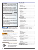
Contents To the Owner: Thank you for purchasing a Beckett burner for use with your heating appliance. Please pay attention to the Safety Warnings contained within this instruction manual. Keep this manual for your records and provide it to your qualified service agency for use in professionally setting up and maintaining your oil burner. Your Beckett burner will provide years of efficient operation if it is professionally installed and maintained by a qualified service technician.
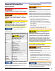
Section: General Information General Information Owner’s Responsibility: Hazard Definitions Indicates a hazardous situation which, if not avoided, will result in death or serious injury. Indicates a hazardous situation, which, if not avoided, could result in death, or serious injury. Follow these instructions exactly. Failure to follow these instructions, misuse, or incorrect adjustment of the burner could result in asphyxiation, explosion or fire.
Section: Pre-Installation Checklist Pre-Installation Checklist Combustion Air Supply Adequate Combustion and Ventilation Air Supply Required Failure to provide adequate air supply could result in asphyxiation, explosion or fire hazards. y The burner cannot properly burn the fuel if it is not supplied with a reliable combustion air source. y Follow the guidelines in the latest editions of the NFPA 31 and CSA-B139 regarding providing adequate air for combustion and ventilation.
Section: Pre-Installation Checklist Vent System Table 1 – Nozzle Capacities Rated gph @100 125 psig The flue gas venting system must be in good condition and must comply with all applicable codes. Pressure - Pounds per square inch 140 150 175 200 250 275 300 3.00 3.35 3.55 3.67 3.97 4.24 4.74 4.97 5.20 3.50 3.91 4.14 4.29 4.63 4.95 5.53 5.80 6.06 4.00 4.47 4.73 4.90 5.29 5.66 6.32 6.63 6.93 4.50 5.04 5.32 5.51 5.95 6.36 7.11 7.46 7.79 5.00 5.59 5.92 6.12 6.
Section: Pre-Installation Checklist Figure 2 - Dimensions: Minimum Combustion Chamber and Air Tube Mounting. ○ The CF1400 maximum firing capacity depends on the firebox pressure. Use Table 2 to verify the correct air tube type for the firing rate required. Use Tube B only when Tube A cannot provide the firing rate required. ○ On the CF2300, there are two tube arrangements available – - Tube A — 7.0 to 19.9 GPH per Figure 3. - Tube B — 10.0 to 19.9 GPH per Figure 3.
Section: Mount the Burner Maximum Firing Rate U.S. GPH Figure 3a - Firebox Pressure: CF1400 with no Reserve Air 15 Protect the air tube from overheating. Overheating could cause damage to the air tube and other combustion components leading to equipment malfunction and impaired combustion performance. 14 13 KE 12 KD 11 10 9 0.0 0.2 0.4 0.6 0.8 1.0 Firebox Pressure in Inches Water Column (W.C.) Maximum Firing Rate U.S.
Section: Mount the Burner Mount Air Tube to Burner Remove the rear access door from the back of the burner for improved access to the interior. Attach the air tube to the burner with the bolts and acorn nuts provided. The acorn nuts must go on the outside of the burner, with the bolts inserted from the inside. ○ ○ Install Nozzle See Figure 5. Install the oil nozzle in the nozzle adapter. Use a 3/4” open-end wrench to steady the nozzle adapter and a 5/8” open-end wrench to turn the nozzle.
Section: Mount the Burner Figure 7 – Adjusting Plate Assy. d b e f Figure 8 – Burner Installed in Appliance Front c g #9 Setting Set “Z” Dimension 1. Replace the rear access door on the burner, making sure that the adjusting plate assembly is seated in the recessed area in the housing. 2. Loosen acorn nut (item c) and spline nut (item b). Move nozzle line forward to the maximum head setting #9 and tighten acorn nut (item c). 3. Loosen acorn nut (item d).
Section: Mount the Burner Special Note: The burner is shipped with a bypass plug installed in the fuel unit. For low/high operation, the by-pass plug must be left in the fuel unit, regardless of the fuel system used (one-pipe with by-pass loop or two-pipe). Do not remove the by-pass plug. ○ ○ One-pipe Oil System By-pass Loop Refer to Figure 9 (item m). Note the addition of a fieldinstalled by-pass loop (use 3/8” copper tubing) from the fuel unit Return port to the Inlet port.
Section: Wire the Burner Low-fire/high-fire operation – The fuel unit nozzle port pressure is factory set at 300 psig. ○ At high fire, full pressure (300 psig) is applied at the oil nozzle, causing full input. ○ At low fire, the by-passing is done inside the fuel unit when the by-pass valve operates. ○ This by-passing of oil reduces the oil pressure at the nozzle (to between 125 psig and 175 psig), reducing the input.
Section: Wire the Burner 6. Run: With a flame established and the control continuing to detect a flame, the burner will operate in the RUN Mode until the load demand is satisfied or a limit opens. a. If terminals RC1 and RC2 are jumpered, the burner operates in the Low-High-Off Mode. The burner starts at Low, goes to High after the flame stabilization period. Flame is extinguished when the load is satisfied or a limit opens, and the burner is sent to motor off delay. b.
Figure 13 – Typical Wiring (7505P) Section: Wire the Burner CF1400/CF2300 Burner Manual 13
Section: Wire the Burner Typical Burner Sequence of Operation 7184B Control Refer to the appliance manufacturer’s wiring diagram for actual specifications. 1. Standby — The burner is idle, waiting for a call for heat. When a call for heat is initiated, there is a 3- to 10-second delay while the control performs a safe start check. 2. Valve-on delay — As applicable, the ignition and motor are turned on for a 15-second prepurge. 3. Trial for ignition (TFI) — The fuel valve is opened, as applicable.
Section: Prepare the Burner for Start-up complete heat cycle between attempts, the lockout becomes restricted. A qualified service technician should be called to inspect the burner.
Section: Prepare the Burner for Start-up Initial Head Position Figure 16 – Adjusting Plate Initial Setting, Typical The indicator plate assembly (item e) markings correspond to head position settings (Figure 16). ○ Slide the secondary adjusting plate (item f) toward the rear of the burner until the number on the indicator plate corresponds to the initial head setting given in Tables 4a and 4b for the desired firing rate and burner (high-fire).
Section: Prepare the Burner for Start-up Initial Air Settings If your burner was built for a specific OEM (Original Equipment Manufacturer) application, the “Mfr’s Settings” label (see Figure 1) will indicate the application and the initial air settings made at Beckett. Please verify those settings using the following procedure.
Section: Start the Burner Start the Burner Start Burner and Vent Air From Oil Line Hot Gas Puff-back and Heavy Smoke Hazard Explosion and Fire Hazard Failure to follow these instructions could lead to equipment malfunction and result in heavy smoke emission, soot-up, hot gas puff-back, fire and asphyxiation hazards. y Do not attempt to start the burner when excess oil has accumulated in the appliance, the appliance is full of vapor, or when the combustion chamber is very hot.
Section: Start the Burner Operating the Burner 1. Move the low-fire hold switch to the low fire hold position (to hold burner in low fire when started). 2. Verify that the air adjusting cam (Figure 17, item d) has been set to the initial low-fire air setting as described under the ‘Initial Air Settings’ section. 3. Open the oil shutoff valves in the oil supply line to the burner. 4. Set the thermostat (or operating control) to call for heat. 5. Close the line switch to the burner.
Section: Maintenance and Service Maintenance and Service Annual Professional Service Required Tampering with or making incorrect adjustments could lead to equipment malfunction and result in asphyxiation, explosion or fire. y Do not tamper with the burner or controls or make any adjustments unless you are a trained and qualified service technician. y To ensure continued reliable operation, a qualified service technician must service this burner annually.
Section: Replacement Parts Figure 19a – Burner Replacement Parts 1 2 3 4 6 5 SK9930 7 8 9 SK9931 CF1400/CF2300 Burner Manual 21
Replacement Parts For best performance specify genuine Beckett replacement parts Item Part Name Description CF1400 Part No. CF2300 Part No. 1 Oil Valve Mounted on Junction Box 21789U 21789U 2 Knurled Nut All models 3666 3666 3 Adjusting plate assembly w/ cast aluminum door w/ stamped sheet-metal door 51213U 5201701U 51213U 5201701U 4 Fuel pump B2TA-8245 21313U 21313U 5 Damper motor 2-stage 750601U 750601U 6 Fuel lines Specify length – – 7 Air Proving Switch 2” W.C.
Figure 19b – Burner Replacement Parts (Continued) 14 10 13 12 11 SK9930 17 16 15 19 SK9936 18 20 21 22 23 SK9932 CF1400/CF2300 Burner Manual 23
Limited Warranty Information The R. W. BECKETT CORPORATION (“Beckett”) warrants to persons who purchase its “Products” from Beckett for resale, or for incorporation into a product for resale (“Customers”), that its equipment is free from defects in material and workmanship. To qualify for warranty benefits, products must be installed by a qualified service agency in full compliance with all codes and authorities having jurisdiction, and used within the tolerances of Beckett’s defined product specifications.