RWF40 Hints Manual This RWF40 Hints Manual is intended for use by OEMs which integrate the controller into their products! CC1B-Hints-en Preliminary 04.02.
This page is intentionally left blank… 2/16 CC1B-Hints-en Preliminary 04.02.
Contents 1. Introduction to hints manual.........................................................................................3 1.1.1 How to use this manual ....................................................................................................................................................................3 1.1.2 Symbols used in this manual ....................................................................................................................................................
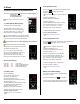
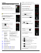
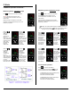
2.1.3 Parameter Level 2. Hints 2.1 Getting started with the RWF40 menu The RWF40 menu system has three Levels, beyond the Basic Display, the User Level, the Parameter Level and the Configuration Level. RWF40 user manual Section 6 Operation. 2.1.1 Start with the Basic Display Shown at the right is the basic display. The upper, larger, 4 digit red LEDs, (180) will be referred to as, the ‘Actual value display’. The lower, smaller, 4 digit green LEDs, (180) will be referred to as, the ‘Setpoint display’.
Example 2. Hints 2.2 How to configure your RWF40 Re-configure (adjust) the value for C111 If no keys are pressed for 30 seconds, at anytime, the controller will automatically return to the basic display. Shown at the right is the basic display. The current value of C111, (9030) is shown in the actual value display. The current configuration of your specific controller will determine which levels you will be allowed to access. The current configuration item (C111) is shown in the setpoint display.
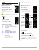
Example 2. Hints Adjust the value for parameter AL. 2.3 How to adjust parameters RWF40 user manual Section 6.3 If no keys are pressed for 30 seconds, at anytime, the controller will automatically return to the basic display. Shown at the right is the basic display. The current value of AL, (0) is shown in the actual value display. The current configuration of your specific controller will determine which levels you will be allowed to access.
Example 2. Hints 2.4 How to change a setpoint Adjust the value for parameter AL. If no keys are pressed for 30 seconds, at anytime, the controller will automatically return to the basic display. (SP1, SP2, or dSP) RWF40 user manual Section 6.2 The current value of AL, (0) is shown in the actual value display. Shown at the right is the basic display. The current parameter item (AL) is shown in the setpoint display.
2. Hints 2.5 How to display the software version and units RWF40 user manual Section 6.2 .5 Shown at the right is the basic display. The current configuration of your specific controller will determine which levels you will be allowed to access. 2.6 Manual operation A C112 of xxx3 will prevent use of the keys. RWF40 user manual Section 6.2 .2 and 6.2.3. The C112 locking code can only be adjusted by the manufacturer. Shown at the right is the basic display.
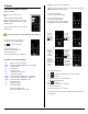
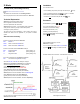
2. Hints 2.6 Manual operation continued… Modulating burner, 3-Position output Press and hold for 5 seconds, and release. Modulating burner, Modulating output Press and hold for 5 seconds, and release. The red LED above the manual icon turns on to indicate that the controller is now in the manual mode. The red LED above the manual icon turns on to indicate that the controller is now in the manual mode.
2. Hints Conditions 2.7 Auto-tune (self-setting function) The controller must be : - in the modulating output mode (D1 is open and the step icon RWF40 user manual section 6.2.4 and 9.1 The RWF40 User manual refers to a ‘self-setting-function’ that for the purposes of this manual will be refered to as ‘Auto-tune’.
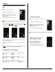
Set parameters 2. Hints See Hint section 2.3, ‘How to adjust parameters’ 2.8 Setting up a standard temperature application The actual value display, (0) shows the current parameter value. Using a 1000 ohm Ni RTD, L & S # 556-541 –13 °F to +203 °F The setpoint display, (AL) shows the parameter item you are adjusting. Configure Increase or decrease the value, accept it by waiting 2 seconds. If no keys are pressed for 20 seconds, the controller will exit this mode, and return to the basic display.
Set parameters 2. Hints 2.9 Setting up a standard pressure application See Hint section 2.3, ‘How to adjust parameters’ Using a QBE sensor, Siemens part # QBE620-P10 [P10 is 150PSI] The actual value display, (0) shows the current parameter value. Configure The setpoint display, (AL) shows the parameter item you are adjusting. If no keys are pressed for 20 seconds, the controller will exit this mode, and return to the basic display. Increase or decrease the value, accept it by waiting 2 seconds.
3. Notes 3.1 Logic summary 12/16 K6 AL function Terminals Q64 & Q65.. , lk1 thru lk8 CC1B-Hints-en Preliminary 04.02.
3. Notes 3.2 Your record of values RWF40 Man. Ref. Sec 8.1 Sec 8.1 / 8.2 Sec 8.1 Sec 8.3.1 Sec 8.3.2 Sec 8.3.3 Sec 8.3.4 Sec 8.3.5 Sec 8.3.
Siemens Building Technologies Landis & Staefa Produktion GmbH Berliner Ring 23 D - 76347 Rastatt Tel. 0049 - 7222 - 598 - 0 Fax. 0049 - 7222 – 598 269 2002 Siemens Building Technologies Subject to change! http://www.landisstaefa.com 14/16 CC1B-Hints-en Preliminary 04.02.