Installation and Operating instructions for CP29xx Multi-touch built-in Control Panel with DVI/ USB Extended interface Version: 1.
Table of contents Table of contents 1 Foreword 1.1 3 Notes on the Documentation 3 1.1.1 Liability Conditions 3 1.1.2 Trademarks 3 1.1.3 Patent Pending 3 1.1.4 Copyright 3 1.1.5 State at Delivery 3 1.1.6 Delivery conditions 3 1.2 Description of safety symbols 4 1.3 Basic safety measures 5 1.4 Operator’s obligation to exercise diligence 6 1.4.1 National regulations 6 1.4.2 Procedure in the event of a fault 6 1.4.3 Operator requirements 6 2 Product Description 7 2.
Table of contents 4.2 4.1.4 Mounting of the Control Panel 14 4.1.5 Fitting the power supply cable 15 Connecting the Control Panel 16 4.2.1 Connecting cables 16 4.2.2 Protective Earthing 16 5 Operating Instructions 5.1 5.2 5.3 17 Switching the Control Panel on and off 17 5.1.1 Switching on 17 5.1.2 Shutting down and switching off 17 Operation 17 5.2.1 17 Setting the transmission rate Servicing and maintenance 18 5.3.1 Cleaning 18 5.3.2 Maintenance 18 5.
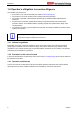
Foreword 1 Foreword 1.1 Notes on the Documentation This description is only intended for the use of trained specialists in control and automation engineering who are familiar with the applicable national standards. It is essential that the following notes and explanations are followed when installing and commissioning these components.
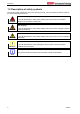
Foreword 1.2 Description of safety symbols The following safety symbols are used in this operating manual. They are intended to alert the reader to the associated safety instructions.
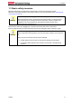
Foreword 1.3 Basic safety measures Before the Industrial PC is switched off, software that is running must be properly closed. Otherwise it is possible that data on the storage medium is lost. Please read the section Switching the Control Panel on and off.
Foreword 1.
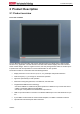
Product Description 2 Product Description 2.1 Product overview Front view of CP29xx The new Beckhoff panel generation with industry-standard multi-touch display offers a feature-laden solution for any application. The wide selection of models offers different display sizes and formats as well as custom designs. Even for single-touch users, this new panel generation offers an excellent priceto-performance ratio and represents an economical alternative to other systems.
Product Description 2.2 Appropriate Use The multi-touch built-in Control Panel CP29xx is designed for industrial application in machine and plant engineering. A multi-touch display is accommodated in a stainless steel housing. The Control Panel is installed in the front of control cabinets. The DVI/USB extension technology integrated in the CP29xx Control Panel enables remote Panel operation at a distance of up to 50 m from the PC via a standard cable.
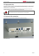
Product Description 2.4 Interfaces X106 DVI-E Input X105 USB-E Input X104 USB in X102, Ground X103 USB out X101 Power 2.4.1 DVI-E Input (Digital Visual Interface-Extended) (X106) X106 DVI-D 3 X 8-pole digital PCB installation (MOLEX 74320-9000 / 74320-9004) The DVI-E connection (X 106) is used for transferring the video signal from the Industrial PC to the Control Panel. The graphics signal is transferred directly via a DVI cable over a distance of 50 m max.
Product Description 2.4.2 USB-Extended Input (X 105) X105 Connection via standard-RJ45-cabel, not crossed The Control Panel is connected with the CU8801 USB to USB extended converter box via the USBExtended input (X 105). In order to realize a distance of 50 m without hubs, with USB extended the USB signal is converted so that it can be transferred via 50 m CAT5 cables commonly used for Ethernet wiring. In the Control Panel the signal is converted back to USB. 2.4.
Product Description 2.5 Connection Kits/ Connection Cables One 5-pole power supply connector is provided with the Control Panel. Optionally prefabricated connection kits for the DVI-E/ USB-E connection are available. 2.5.
Installation 3 Installation 3.1 Transport and Unpacking The specified storage conditions must be observed (see chapter Technical Data). 3.1.1 Transport Despite the robust design of the unit, the components are sensitive to strong vibrations and impacts. During transport, your Control Panel should therefore be protected from excessive mechanical stress. Therefore, please use the original packaging.
Mounting 4 Mounting The Control Panel CP29xx is designed for mounting in control cabinets in machine and plant engineering applications. The ambient conditions specified for operation must be observed (see chapter Technical Data). 4.1 Installation in the control cabinet 4.1.1 Preparation of the control cabinet The control cabinet wall must be prepared with the required mounting opening according to the Control Panel’s dimensions (see chapter Assembly dimensions).
Mounting 4.1.4 Mounting of the Control Panel The Control Panel is installed in the cabinet wall with clamping levers. For the cutout dimension of the Control Panel see chapter Assembly dimensions, the wall thickness is between 1 mm and 5 mm. 1. Insert the Control Panel into the cutout. 2. Release the clamping levers with a 3.0 mm Allen key. 3. Turn the clamping levers to the side through 90°. 4. Retighten the screws.
Mounting 4.1.5 Fitting the power supply cable Fit the cables for the power supply of the Control Panel, using the included material for assembling the connectors: Material for assembling the connector Plug connector 5-pole Stain relief housing with lacing cord Conductive cross-section The connector is specified for 16 A and can lift conductive cross-sections until 1.5 mm2. Note So the connector is fitted to the cable 1. Strip insulation from the cable ends (Length of stripped conductor is 8 - 9 mm). 2.
Mounting 4.2 Connecting the Control Panel Risk of explosion! Danger The Control Panel must never be connected or disconnected in an area that is subject to explosion hazard! The mains plug must be disconnected Please read the documentation for the external devices prior to connecting them! Attention During thunderstorms, plug connector must neither be inserted nor removed! When disconnecting a plug connector, always handle it at the plug. Do not pull the cable! 4.2.
Operating Instructions 5 Operating Instructions 5.1 Switching the Control Panel on and off 5.1.1 Switching on The Control Panel does not have its own mains power switch. As soon as the power supply is switched on the Control Panel is activated. 5.1.2 Shutting down and switching off Control software such as is typically used on Industrial PCs permits various users to be given different rights.
Operating Instructions 5.3 Servicing and maintenance 5.3.1 Cleaning Disconnect power supply DANGER Switch off the device and all connected devices, and disconnect the device from the power supply. The device can be cleaned with a soft, damp cleaning cloth. Do not use any aggressive cleaning materials, thinners, scouring material or hard objects that could cause scratches. 5.3.2 Maintenance The Control Panel is maintenance-free. 5.
Troubleshooting 6 Troubleshooting Pixel errors Note Pixel errors in the TFT display are production-caused and represent no complaintreason! Anomalies of the Touchscreen Note Anomalies of the touchscreen sensor are production-caused and represent no complaint-reason! Fault Cause Measures The Control Panel shows no function No power supply to the Control Panel/ Industrial PC Check power supply cable Cable not connected 1. 2.
Assembly dimensions 7 Assembly dimensions CP2907 with 7“ display, landscape (all dimensions are in mm) Notice mounting orientation The assembly of the unit must take place with the orientation diagrammed here.
Assembly dimensions CP2915 with 15“ display, landscape (all dimensions are in mm) Notice mounting orientation The assembly of the unit must take place with the orientation diagrammed here.
Assembly dimensions CP2915 with 15“ display, portrait (all dimensions are in mm) Notice mounting orientation The assembly of the unit must take place with the orientation diagrammed here.
Assembly dimensions CP2916 with 15.6“ display, landscape (all dimensions are in mm) Notice mounting orientation The assembly of the unit must take place with the orientation diagrammed here.
Assembly dimensions CP2918 with 18.5“ display, landscape (all dimensions are in mm) Notice mounting orientation The assembly of the unit must take place with the orientation diagrammed here.
Assembly dimensions CP2918 with 18.5“ display, portrait (all dimensions are in mm) Notice mounting orientation The assembly of the unit must take place with the orientation diagrammed here.
Assembly dimensions CP2919 with 19“ display, landscape (all dimensions are in mm) Notice mounting orientation The assembly of the unit must take place with the orientation diagrammed here.
Assembly dimensions CP2921 with 21.5“ display, landscape (all dimensions are in mm) Notice mounting orientation The assembly of the unit must take place with the orientation diagrammed here.
Assembly dimensions CP2924 with 24“ display, landscape (all dimensions are in mm) Notice mounting orientation The assembly of the unit must take place with the orientation diagrammed here.
Technical Data 8 Technical Data Risk of explosion! Do not use the Control Panel in areas of explosive hazard! Danger Pixel errors Note Pixel errors in the TFT display are production-caused and represent no complaintreason! Anomalies of the Touchscreen Note Anomalies of the touchscreen sensor are production-caused and represent no complaint-reason! Product name CP29xx Dimensions (B x H x T) See chapter Assembly dimensions Weight CP2907: CP2912: CP2915: CP2916: Supply voltage 24 VDC (20.4 – 28.
Appendix 9 Appendix 9.1 Beckhoff Support and Service Beckhoff and their partners around the world offer comprehensive support and service, making available fast and competent assistance with all questions related to Beckhoff products and system solutions. 9.1.
Appendix 9.2 Approvals for USA and Canada 9.3 FCC Approvals for the United States of America FCC: Federal Communications Commission Radio Frequency Interference Statement This equipment has been tested and found to comply with the limits for a Class A digital device, pursuant to Part 15 of the FCC Rules. These limits are designed to provide reasonable protection against harmful interference when the equipment is operated in a commercial environment.