
Specifications


Beech Ovens Page 58 28/07/2011 (C)
RND-REC-RGO Manual (R1) Confidential and Proprietary
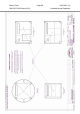
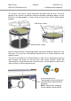
Spray Filter Connection
The diagram below shows the connection location for the spray filter services.
The services details are outlined in the Spray Filter – Technical Specifications
section of this manual.
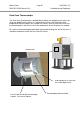
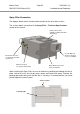
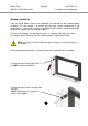
When installing the Spray Filter, be sure to remove any packing tape holding the filter in
place. Loosen the nuts on the top access panel and remove the panel. Remove the
packing tape and making sure that the filter is securely in its correct position (as shown
below) replace the access panel.
Water Connection
(½” (15mm) Connection)
Electrical Connection
(To be interlocked with
exhaust fan)
Waste Water Connection
(11/2” Connection)
Cool Air Make-up
(Ensure a fresh air
source is available)
Exhaust Connection
(300mm x 300mm standard
duct flange)
Packing tape
Access panel