
Instructions


3
1
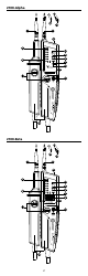
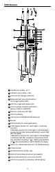
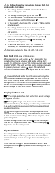
Handle test probe - (L1)
2
Indicator test probe + (L2)
3
LED row for voltage indicator
4
Measurement area illumination /
Torch light (white LED)
5
LED for single-pole phase test
6
LED for phase rotation indication
(phase rotation right/left)
7
LED for continuity test (Rx)
8
LED for polarity
9
LCD screen (2100-Beta/2100-Gamma)
10
Buzzer
11
Push buttons for load application
12
2100-Alpha: Button for torch light / continuity
test (Rx)
2100-Beta: Button for torch light / LCD backlight /
continuity test (Rx), data hold (HOLD), switch ON/
OFF the Tester
2100-Gamma: Button for torch light / LCD backlight
/ continuity test (Rx), resistance measurement (Ω) /
low resistance indication “
”, cable break detector
/ EF
, data hold (HOLD), switch ON/OFF the Tester
13
Sensor for cable break detector / EF (2100-Gamma)
14
Probe handle
15
GS 38 protective probe caps
16
4mm Ø test probe extension (screwable)
17
Test probe protector cover (not shown)
18
LED for low battery indication (2100-Alpha)
2100-Gamma
RL
2100
4
3
8
11
14
12
13
6
5
9
7
10
16
15
1 2