AMP-330 AMP-330-EUR 1000A ACDC TRMS CAT IV Clamp Multimeter MAX 1000A 1000V CAT III 600V CAT IV NCV(EF) OFF HOLD TRMS ZERO PEAK-RMS REC COM CREST SELECT CAT III 1000V CAT IV 600V Hz
AMP-330 / AMP-330-EUR 1000A ACDC TRMS CAT IV Clamp Multimeter English User Manual 7/2014, 6003318 A ©2014 Amprobe Test Tools. All rights reserved.
Limited Warranty and Limitation of Liability Your Amprobe product will be free from defects in material and workmanship for one year from the date of purchase unless local laws require otherwise. This warranty does not cover fuses, disposable batteries or damage from accident, neglect, misuse, alteration, contamination, or abnormal conditions of operation or handling. Resellers are not authorized to extend any other warranty on the behalf of Amprobe.
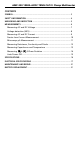
AMP-330 1000A ACDC TRMS CAT IV Clamp Multimeter CONTENTS SYMBOL.......................................................................................................... 3 SAFETY INFORMATION.................................................................................. 4 UNPACKING AND INSPECTION...................................................................... 5 MEASUREMENTS............................................................................................ 6 Measuring AC and DC Voltage......
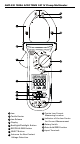
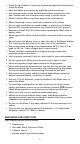
AMP-330 1000A ACDC TRMS CAT IV Clamp Multimeter 8 9 1 10 2 1 3 11 12 1 4 5 1 1 6 7 13 1 Jaw 2 Tactile Barrier 3 Jaw Release 4 Display 5 Backlight/Flashlight Button 6 REC/PEAK-RMS Button 7 SELECT Button 8 Antenna for Non-Contact Voltage Detection 9 Precise Low Current Measuring Location 10 Indicator of the Jaw Center for Current Measurement 11 Rotary Switch 12 Data Hold/ZERO button 13 Input Terminals
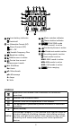
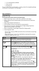
26 25 24 23 14 22 21 15 16 17 20 18 14 19 Low battery indicator 21 Data hold 15 22 Alternative Current (AC) Direct Current (DC) 23 AC + DC 24 Varable Frequency Dive 16 Negative reading 17 Relative zero is active 18 25 Motor rotation indicator Phase rotation indicator PEAK-RMS mode (in-rush current) is active Continuity buzzer is active Diode test mode is active Recording mode is active Crest mode is active MAX: MAX mode is active Precise low current measurement mode MIN: MIN mode is a
CAT III Overvoltage Category lll is for equipment intended to form part of a building wiring installation. Such equipment includes socket outlets, fuse panels, and some mains installation control equipment. B F Alternating Current (AC). N Battery. Direct Current (DC). Underwriters Laboratories. [Note: Canadian and US.] P Complies with European Directives. Conforms to relevant Australian standards. = Do not dispose this product as unsorted municipal waste. Contact aqualified recycler.
• Check the test leads for continuity. Replace damaged test leads before using the Meter. • Have the Meter serviced only by qualified service personnel. • Use extreme caution when working around bare conductors or bus bars. Contact with the conductor could result in electric shock. • Do not hold the Meter anywhere beyond the tactile barrier. • When measuring current, center the conductor in the clamp.
1 1.5 V AA batteries (installed) 1 Users manual 1 Carrying case If any of these items are damaged or missing, return the complete package to the place of purchase for an exchange. MEASUREMENTS � Warning To avoid possible electric shock or personal injury: • When measuring current, center the conductor in the clamp. • When making current measurements, disconnect the test leads from the Meter. • Keep fingers behind Tactile Barrier. • Use the proper function and range for measurements.
REC / PEAK-RMS Press REC button to activate maximum, minimum and average reading memory mode ( MAX MIN AVG is displayed). The meter beeps when MAX and MIN reading is updated during measurement. Press REC button again to read the MAX, MIN and AVG reading in sequence. Press REC button > one second to exit MAX/MIN/AVG reading memory mode. Press REC / PEAK-RMS button > one second to enter is displayed) to capture PEAK-RMS mode ( inrush current or voltage RMS values (80 ms).
Note: • AC V (and hence DC+AC V and Hz) function is equipped with digital low-pass filter, and is capable of dealing with VFD (Variable Frequency Drives) signals. It also improves AC V reading stability in noisy electrical environments. Voltage Detection (NCV) Non-Contact Voltage Detection: 1. Turn the rotary switch to NCV (EF). Press SELECT button to toggle NCV (EF) mode (“EF” is displayed). 2.
Measuring AC and DC Current � Warning To avoid electrical shock and injury: • Remove Test Leads before making current measurements. • Do not hold the Meter anywhere beyond the tactile barrier. • Do not use the Meter to measure currents above the maximum rated frequency (400Hz). Circulating currents may cause the magnetic circuits of the Jaws reach hazardous excessive temperatures. To measure AC or DC current: 1. Turn the rotary function switch to . 2.
� Caution During current measurement keep the jaws away from other currentcarrying devices such as transformers, motors or energized wires, as they may negatively influence accuracy of the measurement. Precise Low-Current Measurement � Warning To avoid electrical shock and injury: • Remove Test Leads before making current measurements. • Do not hold the Meter anywhere beyond the tactile barrier. • Do not use the Meter to measure currents above the maximum rated frequency (400Hz).
� Caution During current measurement keep the jaws away from other currentcarrying devices such as transformers, motors or energized wires, as they may negatively influence accuracy of the measurement. Microamps μA Measurement The μA DC ( ) function on the Meter is primarily for HVAC flame sensor testing. To test a heating system flame sensor: 1. Turn the heating unit off and locate the wire between the gas-burner controller and the flame sensor. 2. Disconnect one of the flame sensor wires. 3.
Measuring Resistance, Continuity and Diode � Warning • To avoid false readings that can lead to electrical shock and injury, deenergize the circuit before taking the measurement. • To avoid electrical shock when testing resistance/continuity/diode in a circuit, make sure the power to the circuit is turned off and all capacitors are discharged. Use DC voltage function to check the capacitors are discharged. 1. Connect the black test lead to the COM terminal and the red test lead to the Ω terminal. 2.
Measuring Capacitance and Temperature � Warning To avoid electrical shock and injury: • When testing capacitor in a circuit, make sure the power to the circuit is turned off and all capacitors are discharged. • When measuring temperature, DO NOT apply the temperature probe to any live conductive parts. Capacitance 1. Turn off circuit power, then disconnect and discharge the capacitor before measuring capacitance. 2. Connect the black test lead to the COM terminal and the red test lead terminal to the 3.
Measuring & 3-Phase Rotation Measurement is made through the Meter’s terminals L1/L2/L3. Phase Rotation directions are indicated as symbolic (LCD segments) movements on the display. Default mode at . Press SELECT button to toggle between and modes. : Hi-sensitivity mode for checking phase rotation of Motors detects relatively low signal outputs generated spinning a motor shaft,. : Normal-sensitivity mode for identifying phase sequence of 3-phase MAINS supply.
Normal mode for the MAINS circuit: Connect the test lead L1/L2/L3 to the 3-phase mains circuit by using probes and/or alligator clips. If the meter indicates a clockwise movement, the phases connected to L1, L2 and L3 of the meter are L1, L2 and L3 (also known as R, S and T), respectively. If the meter indicates a counter-clockwise movement, swap any two connects between the meter and phases. Then retest.
SPECIFICATIONS Display 3-5/6 digits 6000 counts Sensing True RMS Polarity Automatic Update rate 5 per second nominal Operating temperature 14 °F to 122 °F (-10 °C to 50 °C) Relative humidity Non condensing ≤ 10 °C, 10 °C to 30 °C ≤ 90%, 30 °C to 40 °C ≤ 75%, 40 °C to 50 °C ≤ 45% Storage temperature -4 °F to 140 °F (-20 °C to 60 °C), < 80% R.H. (with battery removed) Pollution degree 2 Operating altitude ≤ 2000 m (storage below 12000 m) Temperature coefficient nominal 0.
Dimension (L x W x H) 10.16 x 3.70 x 1.73 in (258 x 94 x 44 mm) Weight 420 g (0.93 lb) Jaw opening & conductor diameter 2.0 in (51 mm) max. ELECTRICAL SPECIFICATIONS Accuracy is ± (% reading digits + number of digits) or otherwise specified at 23°C ± 5°C. Maximum Crest Factor < 2.5:1 at full scale & < 5:1 at half scale or otherwise specified, and with frequency spectrum not exceeding the specified frequency bandwidth for non-sinusoidal waveforms. DC Voltage Range Accuracy 600.0 V, 1000 V ± (0.
Resistance Range Accuracy 600.0 Ω, 6.000 kΩ, 60.00 kΩ ± (1.0 % + 5 LSD) Open Circuit Voltage: 1.0VDC typical Capacitance Range Accuracy 1) 200.0 µF, 2500 µF ± (2.0 % + 4 LSD) 1)Accuracy with film capacitor or better Diode Range Accuracy 2.000 V ± (1.5 % + 5 LSD) Test Current: 0.3mA typically Open Circuit Voltage: < 3.5VDC typically DC µA Range Accuracy Burden Voltage 200.0 µA, 2000 µA ± (1.0 % + 5 LSD) 3.5 mV/µA Temperature Range Accuracy -40.0 °C to -10.0 °C ±(1% + 1.
Precise Low Current DC Range Accuracy 1) 2) 3) 0.00 A to 20.00 A ± (1.5 % + 5 LSD) >20.00 A to 60.00 A ± (3.0 % + 5 LSD) 1) Induced error from adjacent current-carrying conductor: < 0.02 A/A 2) Specified with DC-zero mode applied to offset the non-zero residual readings, if any 3) Add 10 LSD to the specified accuracy @ < 4 A Precise Low Current DC+AC Range Accuracy 1) 2) 3) 0.00 A to 20.00 A ± (2.0 % + 7 LSD) @ DC, 40 Hz to 100 Hz ± (2.2 % + 7 LSD) @ 100 Hz to 400 Hz >20.00 A to 60.00 A ± (3.
2) Specified with DC-zero mode applied to offset the non-zero residual readings, if any 3) Add 10 LSD to the specified accuracy @ < 9 A 4) Maximum crest factor < 1.4:1 at full scale & < 2.8:1 at half scale Frequency Hz Sensitivity 1) (Sine rms) Range 600 V, 1000 V 50 V 5.00 Hz to 999.9 Hz 60 A (Precise low current) 40 A 40.00 Hz to 400.0 Hz 60 A, 600 A, 1000 A 40 A 40.00 Hz to 400.0 Hz Function Accuracy: ± (1.
Except for the replacement of the battery, repair of the meter should be performed only by a Factory Authorized Service Center or by other qualified instrument service personnel. The front panel and case can be cleaned with a mild solution of detergent and water. Apply sparingly with a soft cloth and allow to dry completely before using. Do not use aromatic hydrocarbons, gasoline or chlorinated solvents for cleaning.
Visit www.Amprobe.com for • • • • Catalog Application notes Product specifications User manuals Amprobe® www.Amprobe.com info@amprobe.com Everett, WA 98203 Tel: 877-AMPROBE (267-7623) Amprobe® Europe Beha-Amprobe In den Engematten 14 79286 Glottertal, Germany Tel.