December 1999 www.behringer.de 1 ENGLISH CX3400 Version 1.
EG-Declaration of Conformity Spezielle Studiotechnik GmbH acc.
SAFETY INSTRUCTIONS CAUTION: To reduce the risk of electrical shock, do not remove the cover (or back). No user serviceable parts inside; refer servicing to qualified personnel. WARNING: To reduce the risk of fire or electrical shock, do not expose this appliance to rain or moisture. This symbol, wherever it appears, alerts you to the presence of uninsulated dangerous voltage inside the enclosure - voltage that may be sufficient to constitute a risk of shock.
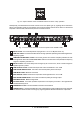
SUPERX PRO ® HIGH-PRECISION STEREO 2-WAY / 3-WAY / MONO 4-WAY CROSSOVER WITH LIMITERS MODEL CX 3400 CX3400 s Professional high-precision stereo 2-way / 3-way / mono 4-way crossover s World-class performance 24 dB per octave Linkwitz-Riley filters s Absolutely flat summed amplitude response, zero phase difference s Individual output level controls for all bands s Individual limiter on each output for optimal loudspeaker protection s Individual output mutes for easy band adjustment s Individual phase reve
FOREWORD Dear Customer, Welcome to the team of SUPER-X PRO users and thank you very much for expressing your confidence in BEHRINGER products by purchasing this crossover. It is one of my most pleasant tasks to write this letter to you, because it is the culmination of many months of hard work delivered by our engineering team to reach a very ambitious goal: making an outstanding device that will become a standard tool used by P.A. companies and studios.
TABLE OF CONTENTS 1. INTRODUCTION ...................................................................................................................... 7 1.1 Multi-way speaker systems ............................................................................................................. 7 1.2 SUPER-X PRO: the high-end frequency crossover ........................................................................ 7 2. THE DESIGN CONCEPT ...................................................................
1. INTRODUCTION Thank you very much for expressing your confidence in BEHRINGER products by purchasing the SUPER-X PRO CX3400. + This manual first describes the terminology used, so that you can fully understand the CX3400 and its functions. Please read the manual carefully and keep it for future reference. 1.1 Multi-way speaker systems Multi-way speaker systems can be found almost everywhere todaynot only in stereo systems, cinemas, discotheques and concert halls.
2.1 Before you begin Your BEHRINGER SUPER-X PRO CX3400 was carefully packed in the factory and the packaging is designed to protect the unit from rough handling. Nevertheless, we recommend that you carefully examine the packaging and its contents for any signs of physical damage, which may have occurred during transit. + If the unit is damaged, please do not return it to BEHRINGER, but notify your dealer and the shipping company immediately, otherwise claims for damage or replacement may not be granted.
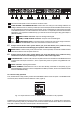
Fig. 2.2: Proper selection of the two MODE buttons for stereo 2-way operation Subsequently, the LEDs above the active controls on the front panel light up, signaling which controls are active in the operating mode you just selected. The functions of these controls can be seen from the second strip label. In stereo mode, both channels perform the same functions. Fig. 2.3: Active control elements on the front panel of the SUPER-X PRO 1 INPUT control.
Fig. 2.4: Active control elements on the rear panel of the SUPER-X PRO 1 Use the enclosed power cord to connect the unit to the mains. 2 FUSE HOLDER / VOLTAGE SELECTOR. Please make sure that your local voltage matches the voltage indicated on the unit, before you attempt to connect and operate the CX3400. Blown fuses may only be replaced by fuses of the same type and rating.
Fig. 2.6: Active control elements on the front panel of the SUPER-X PRO 1 and 2 LOW CUT button. This button activates the 25-Hz high-pass filter protecting the woofers against lowfrequency signals. 3 LOW/MID XOVER FREQ. control. This control governs the crossover frequency between the Low and Mid bands. When the XOVER FREQUENCY button on the rear of the unit is pressed, the frequency range is multiplied by the factor 10. 4 MID/HIGH XOVER FREQ. control.
+ 9 Always switch off the entire system before you press this button, as it produces heavy interference noise that could damage your speakers and/or other equipment. LOW SUM button. In stereo mode, the two Low paths can be summed with the LOW SUM button and routed to the Low output of channel 1, which is particularly useful in systems using additional subwoofers. 12 LOW (LF SUM) OUTPUT connector. Output for the Low band signal. 13 XOVER FREQ. button.
6 LOW OUTPUT control. Controls the output level of the Low band from +6 to -6 dB. 7 LOW PHASE INVERT button. This button reverses the polarity of the Low output. 8 LOW MUTE button. Mutes the Low band. 9 LOW-MID OUTPUT control. Controls the output level of the Low-Mid band from +6 to -6 dB. 10 LOW-MID PHASE INVERT button. This button reverses the polarity of the Low-Mid output. 11 LOW-MID MUTE button. Mutes the Low-Mid band. 15 CD HORN button.
3. APPLICATION 3.1 Tools The following tools are indispensable for a perfect system alignment. You should by all means try to obtain the speaker specifications from the manufacturer, in order to operate the systems in their proper frequency and level ranges. Use the manufacturers documentation to adjust the operating mode and crossover frequencies. + BEHRINGER does not assume any responsibility for speaker damage caused by improper handling of the SUPER-X PRO. 3.1.
3.3.1 Finding drop-outs in the frequency response Check the entire frequency response of the system. Rooms have quite an impact on the frequency response of speaker systems, due to resonance and various reflections. So, you cannot expect to achieve a linear frequency response right from the start. Use an equalizer such as our ULTRA-CURVE PRO DSP8024 or ULTRA-GRAPH GEQ3102.
3.5.2 Basics of electronic runtime correction It is important to know how the dimensions of time and space are connected with each other, e.g. by using a tape measure and a pocket calculator. Example: a delay of 2 ms corresponds to a distance of 68.6 cm; when you measure an offset of 30 cm you can calculate the necessary delay as follows: 2 ms x 30 / 68.6 = 0.87 ms.
Modern systems often use bass reflex cabinets for their woofer or sub-woofer systems. Consequently, when stacking the cabinets, the drivers are usually aligned along the vertical axis of the speaker front, or can at least be aligned using the available control range of the SUPER-X PRO. Here, runtime correction follows the same principle as in midrange/high-midrange/tweeter systems. Problems will be encountered only with unconventional setups (e.g.
The limiter threshold can be set from -6 dB to OFF and acts on all six limiters at the same time. Still, each limiter band works independently, with the LIM-LEDs lighting up as soon as the associated limiter is activated. + Please note that the limiters in the SUPER-X PRO are no hard ratio limiters, i.e. signal peaks can surpass the adjusted threshold by as much as 6 dB. Please make sure that your system provides enough headroom. 3.6.
4.2 Mains connection Before you connect your SUPER-X PRO to the mains, please make sure that your local voltage matches the voltage required by the unit! The fuse holder on the female mains connector has 3 triangular markers, with two of these triangles opposing each other. Your CX3400 is set to the operating voltage printed next to these markers, and can be set to another voltage by turning the fuse holder by 180°. CAUTION: this instruction does not apply to export models exclusively designed, e.g.
Fig. 8.3: Different plug types 5. SPECIFICATIONS INPUT Connectors Type Impedance Max. Input level CMRR XLR Electronically servo-balanced, RF filtered Balanced >50k Ohms, unbalanced >25k Ohms +22 dBu typical, balanced or unbalanced >40 dB, typically >55 dB at 1 kHz OUTPUT Connectors Type Impedance Max. Output Level XLR Electronically servo-balanced, RF filtered Balanced 60 Ohms, unbalanced 30 Ohms +20 dBm balanced/unbalanced 20 4.
PERFORMANCE Bandwidth Frequency Response Signal to Noise Low Output Low-Mid Output Mid Output High-Mid Output High Output Dynamic Range THD & Noise Interchannel Crosstalk 20 Hz to 20 kHz, +0/-0.5 dB <5 Hz to >90 kHz, +0/-3 dB Ref.: +4 dBu, 20 Hz to 20 kHz, unweighted Stereo Mode: Mono Mode: >93 dBu >93 dBu >94 dBu >95 dBu >94 dBu >90 dBu >88 dBu >106 dB, unweighted Limiter Off Limiter On <0.04% <0.
6. WARRANTY § 1 WARRANTY CARD To be protected by this warranty, the buyer must complete and return the enclosed warranty card (signed/stamped by retail dealer) within 14 days of the date of purchase to BEHRINGER INTERNATIONAL (address see § 3). Failure to return the card in due time (date as per postmark) will void any extended warranty claims. adaptation shall not be considered a defect in materials or workmanship.