User´s Manual VIRTUALIZER® DSP1000 English Version 1.0 September 1997 The information contained in this manual is subject to change without notice. No part of this manual may be reproduced or transmitted in any form or by any means, electronic or mechanical, including photocopying and recording of any kind, for any purpose, without the express written permission of Behringer GmbH. ALL RIGHTS RESERVED © 1997 Behringer GmbH. BEHRINGER and VIRTUALIZER are registered trademarks of Behringer.
EG-Declaration of Confirmity Spezielle Studiotechnik GmbH acc.
SAFETY INSTRUCTIONS CAUTION: To reduce the risk of electrical shock, do not remove the cover (or back). No user serviceable parts inside; refer servicing to qualified personnel. WARNING: To reduce the risk of fire or electrical shock, do not expose this appliance to rain or moisture. This symbol, wherever it appears, alerts you to the presence of uninsulated dangerous voltage inside the enclosure - voltage that may be sufficient to constitute a risk of shock.
THE VIRTUALIZER DSP1000 s Ultra-high performance Digital Multi-Effects Processor powerded by a 24-bit high-speed Digital Signal Processor (DSP) s Virtual acoustics reverb algorithms calculated from precise mathematical models of real rooms to give you ultra-natural reverb effects s 32 high quality Reverb, Chorus, Flanger, Delay, Pitch Shifter, Vocoder, Rotary Speaker programs and more s Up to 900 effects variations plus two individual parameters and separate low and high EQ section s Two digital processing
FOREWORD Dear Customer, Welcome to the team of VIRTUALIZER users and thank you very much for expressing your confidence in Behringer products by purchasing this unit. It is one of my most pleasant tasks to write this letter to you, because it is the culmination of many months of hard work for our engineering team.
TABLE OF CONTENT 1. INTRODUCTION..................................................................................................................... 7 1.1 Technical background ...................................................................................................................... 7 1.1.1 Reverberation chambers ........................................................................................................ 8 1.1.2 Spring and plate reverb ................................................
1. INTRODUCTION Since its introduction in the early 80s, artificial digital reverb has been an indispensable standard tool for studio and live applications. Before, professional reverberation could only be produced by using bulky and expensive reverberation plates. With the rapid development of digital technology it has become possible to drastically reduce the price of a good reverb unit, so it is anything but unusual today to find at least one digital reverb device in the racks of P.A.
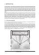
Spatial information is an important means of orientation, because human hearing is also used to determine the position of a sound source. In certain situations, this capability can be very useful or even of vital importance. The fact that we can actually hear the size of a room shows how strongly developed the human sense of hearing actually is. Based on the reflectivity of a room, we can also distinguish (though we often dont know how) the materials it consists of.
1.1.2 Spring and plate reverb Due to the disadvantages of natural reverb chambers (see section 1.1.1), two new methods of generating reverb were invented and used in the 50s and 60s. For the first time ever, plate or spring reverb devices allowed for the artificial production of reverberation. A reverb plate consists of a thin steel plate or sturdy metal sheet coated with a gold alloy, which is set in motion by a generator radiating the signal to be processed (reverberated).
s Pre-delay time: this parameter determines the time between the occurrence of original signal and first reflections. s Decay time: determines the duration of the reverb (in seconds). s High-damp: a function that allows for equalizing the reverberated sound in the higher frequency range. To simulate the sound of a heavily damped room, for instance, the high-frequency portions in the reverb signal must be reduced. 1.
2. THE CONCEPT 2.1 The quality of components and circuits Behringers philosophy guarantees both perfect circuit design and no-compromise selection of components. A 24-bit DSP is used as the heart of the VIRTUALIZER, which is one of the best components available owing to its outstanding specifications and excellent sonic characteristics. Top-quality 20-bit AD/DA converters ensure the high-precision conversion of all signals.
3. INSTALLATION The VIRTUALIZER was carefully packed in the factory and the packaging was designed to protect the unit from rough handling. Nevertheless, we recommend that you carefully examine the packaging and its contents for any signs of physical damage, which may have occurred in transit. + If the unit is damaged, please do not return it to us, but notify your dealer and the shipping company immediately, otherwise claims for damage or replacement may not be granted.
3.4 Selecting the operating level With the Operating Level switch on the rear of the Behringer VIRTUALIZER you can adjust the internal operating level of the unit. Thus, the VIRTUALIZER can be adapted perfectly to various levels (e.g. both the typical home recording level of -10 dBV and the professional studio level of +4 dBu). The LED indicators on the front panel help you optimally adjust the operating level. 3.
4. CONTROL ELEMENTS Fig. 4.1: Front panel control elements The Behringer VIRTUALIZER is equipped with ten parameter keys, one jog wheel (rotary control) and an LED display. Each of the two fully independent channels can be monitored with an 8-stage LED meter. 4.1 Front panel control elements Fig. 4.2: Display section of the VIRTUALIZER 1 The two LED chains read the input signal level in dB relative to nominal level. 2 The EFFECT TABLE gives you an overview of the various effect algorithms.
7 Use the ENGINE L key to select the left audio channel. 8 Use the ENGINE R key to select the right audio channel. If you wish to process the left and right audio channels simultaneously (Couple mode), press both Engine keys at the same time. In Couple mode the LEDs in the Engine keys light up. Whenever you edit one of the two audio channels and then switch to Couple mode, the parameters of the channel last selected will be copied to the other channel. 9 In each preset you can edit two parameters.
4.2 Rear panel control elements Fig. 4.4: Connectors and control elements of the rear panel 16 Use the OPERATING LEVEL switch to adapt the VIRTUALIZER to different operating levels. You can select a -10 dBV semi-pro level used for home recording and a +4 dBu level used in professional studios. The level indicators on the front panel are automatically adapted to read the selected nominal level, i.e. an optimum operating range of the meters is always guaranteed.
5. THE EFFECT ALGORITHMS In a digital effects device all effect programs are based on algorithms computed by a Digital Signal Processor (DSP). How does this work? A DSP can perform an enormous number of binary computations in a minimum amount of time. The binary computations used to generate an effect as part of a program are determined by a so-called algorithm which represents a rule for computing numerical values that are exactly specified for each effect type.
EFFECT ALGORITHM 14 Vocal Distortion 15 Rotary Speaker 16 Vocoder DESCRIPTION Program for distorting vocal sounds, resembles the sound produced by a distorted megaphone. The sound depends largely on the selected variation. A popular effect in combination with organ sounds, as it simulates the sound of a horn-loaded speaker rotating in a wooden cabinet and driven by an electric motor. The resulting sound effect is somewhat similar to a tremolo. Simulation of a "Voice Coder".
Unlike the multi-effects programs, the dual-mode programs (nos. 25 through 32) have their effects split up and sent separately to the two audio channels (left/right). For example, you can route a flanger to the VIRTUALIZERs left channel, while using a reverb (effect #26) for the right channel. In this way, different effects can be routed to the aux busses of your mixing console with only one effects unit.
6. OPERATION 6.1 Effects structure Algorithm type Effects structure In L Reverb + Early Refl. Out L Rev. R Delay, Echo, Flanger, Pitch R In L Delay Out L R Delay R In L Vocoder Rotary Speaker Out L Vocoder R R In L Out L + Rotary Speak. Stereo Phaser R R In L Vocal Distortion + Dist. R In L Serial effect combinations + R Dual Mode effect combinations Effect 1 Flang. + Delay Effect 2 Out L R Out L R In L Effect 1 Out L R Effect 2 R Fig. 6.
VIRTUALIZER enables the preset and the dot disappears. This brief interruption avoids the direct activation of every preset, as you scroll through the preset list with the jog wheel. Otherwise, incomplete "parameter remnants" of presets could reach the audio outputs of the VIRTUALIZER, with possibly disastrous consequences, espcially when using a high-power P.A. system. Thus, the VIRTUALIZER makes sure that no "unwanted" programs are loaded unintentionally.
Display Mode 0 No controller data are transmitted 1 Controller data are received but not transmitted 2 Controller data are transmitted but not received 3 Controller data are transmitted and received Tab. 6.1: Controller settings The fourth page gives you access to the program change setup. The display reads a capital P (=Program).
6.6 The basics of digital signal processing To convert continuous analog signals into a series of digital words, a so-called Analog to Digital Converter (ADC) is used. The converter functions by viewing the signal entering it a given number of times over a period of time, e.g. 44100 times per second, giving a rate of 44.1 kHz, and in each case measuring the signal amplitude, and giving it a numerical value.
an electronic calculator may operate internally with a greater number of decimal places than can be shown on its display). The DSP in the VIRTUALIZER operates with a 24 bit resolution. This is accurate enough to reduce quantizing noise to levels which are usually below the audible threshold. However, when using extreme equalizer settings, some quantizing side effects may be detected. Digital sampling has one further, very disturbing effect: It is very sensitive to signal overload.
7. APPLICATIONS The Behringer VIRTUALIZER is a highly flexible device that can be used for a wide variety of applications. Prior to a presentation of the VIRTUALIZERs many uses, please note the following remarks on how to set signal levels correctly. 7.1 Level setting Take care to set all levels properly on the VIRTUALIZER! Low levels deteriorate the dynamics of the music signal, which results in a poor, weak and noisy sound.
Lets suppose you wish to use the VIRTUALIZER in a live application, interfaced with the f.o.h. mixer, to enhance the guitar sound with a subtle chorus effect. s Connect the VIRTUALIZER to the aux bus of your mixing console (fig. 7.1). Connect the units to the mains and adapt the operating level(s) if necessary (see 3.2 - 3.4). Switch on the VIRTUALIZER and set the levels appropriately (see 7.1). Press the Mix combination to make sure that the unit is set to Mix-Extern mode (see 4.1.1).
7.4 Using the VIRTUALIZER as an effects device for instruments With its extensive MIDI implementation the VIRTUALIZER can also be used, for instance, as a multi-effects device in a guitar rack. Of course, you can wire it both in stereo and mono. Fig. 7.3: Connecting the VIRTUALIZER to a guitar amp (send/return-mono) The following hints illustrate the VIRTUALIZERs versatility if used with a guitar amp. Basically, the VIRTUALIZER should be inserted between the preamp and the power stage.
7.5 Using the VIRTUALIZER in a MIDI system With its built-in MIDI interface the VIRTUALIZER can be integrated into any MIDI system, where it transmits and receives both program change and controller change information to perform program changes via MIDI from a sequencer or any other MIDI device. Wire and set up the VIRTUALIZER as shown below: Fig. 7.4: Connecting the VIRTUALIZER via MIDI to a sequencer/computer and a keyboard (option) 7.
# DSP PRG 1 A 2 B 3 A 4 B 5 B 6 C 7 B 8 C 9 A 10 D 11 D 12 B 13 B 14 H 15 G 16 F 17 D 18 D 19 D 20 D 21 E 22 C 23 C 24 C 25 C 26 C 27 C 28 C 29 E 30 D 31 D 32 D VARIATION CATHEDRAL Reverb Time PLATE Reverb Time SMALL HALL Reverb Time ROOM Reverb Time STUDIO Reverb Time CONCERT Reverb Time STAGE Reverb Time VOCAL Reverb Time PERCUSSION Reverb Time DELAY ECHO GATED REVERB Gate Time REVERSE REVERB Gate Time VOCAL DISTORTION Distortion Type ROTARY SPEAKER Rotary Type VOCODER Vocoder Type PITCH FLANGER Mod.
8.2 MIDI Implementation Function Transmitted Recognized Basic Channel Default Changed Default Messages Altered Mode Note Number Velocity After Touch OFF, 1 - 16 OFF, 1 - 16 1,2,3,4 X X X X X X X X X O 20 - 30 O (0-99) 1-100 X X X X X X X X X X True Voice Note ON Note OFF Key´s Ch´s Pitch Bender Control Progr.
8.3 Specifications Analog Inputs Type Impedance Nominal Operating Level Max. Input Level 1/4 TRS unbalanced 100 kOhms -10dBV to +4dBu +16 dBu Analog Outputs Type Impedance Max. Output Level Bandwidth THD+N @ 1kHz / +10 dBu S/N Ratio @ 1 kHz / +10 dBu Crosstalk @ 1kHz 1/4 TRS unbalanced 100 Ohms +16 dBu 20 Hz to 20 kHz (+0/-0.5 dB) 0.
9. WARRANTY § 1 WARRANTY CARD To be protected by this warranty, the buyer must complete and return the enclosed warranty card (signed/ stamped by retail dealer) within 14 days of the date of purchase to Behringer GmbH (address see § 3). Failure to return the card in due time (date as per postmark) will void any extended warranty claims.
be invoiced separately when the buyer has sent in a written repair order. § 5 WARRANTY TRANSFERABILITY This warranty is extended exclusively to the original buyer (customer of retail dealer) and is not transferable to anyone who may subsequently purchase this product. No other person (retail dealer, etc.) shall be entitled to give any warranty promise on behalf of Behringer GmbH.