
Manual
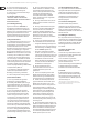

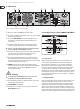

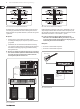
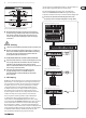
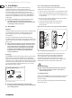


Table Of Contents

11 EUROPOWER EP4000/EP2000 Bedienungsanleitung
4.2 Audioverbindungen
Für die verschiedenen Anwendungen benötigen Sie eine Vielzahl von
unterschiedlichen Kabeln. Die folgende Abbildung zeigt Ihnen, wie diese
Kabel beschaen sein müssen. Achten Sie darauf, stets hochwertige Kabel
zuverwenden.
◊ Wenn Sie ein symmetrisches Eingangssignal anlegen, verwenden Sie
bitte auch ausschließlich symmetrische Kabel zur Weiterverbindung,
da auch nur ein einziges unsymmetrisch beschaltetes Kabel das
Gesamtsignal unsymmetrisch werden lässt.
output
For unbalanced use, pin 1 and pin 3
have to be bridged
1 = ground/shield
2 = hot (+ve)
3 = cold (-ve)
input
12
3
1
2
3
Balanced use with XLR connectors
Abb. 4.3: XLR-Verbindungen
strain relief clamp
sleeve
tip
sleeve
(ground/shield)
Unbalanced ¼" TS connector
tip
(signal)
Abb. 4.4: 6,3-mm-Monoklinkenstecker
strain relief clamp
sleeve
ring
tip
sleeve
ground/shield
For connection of balanced and unbalanced plugs,
ring and sleeve have to be bridged at the stereo plug.
Balanced ¼" TRS connector
ring
cold (-ve)
tip
hot (+ve)
Abb. 4.5: 6,3-mm-Stereoklinkenstecker
5. Technische Daten
Ausgangsleistung
RMS @ 1% Klirrfaktor (Sinuswelle), Beide Kanäle Betrieben
EP4000
8 Ω pro Kanal 550 W
4 Ω pro Kanal 950 W
2 Ω pro Kanal 1250 W
EP2000
8 Ω pro Kanal 350 W
4 Ω pro Kanal 500 W
2 Ω pro Kanal 650 W
RMS @ 1% Klirrfaktor (Sinuswelle), Gebrückter Modus
EP4000
8 Ω 1750 W
4 Ω 2400 W
EP2000
8 Ω 1000 W
4 Ω 1300 W
Spitzenleistung, Beide Kanäle Betrieben
EP4000
8 Ω pro Kanal 750 W
4 Ω pro Kanal 1400 W
2 Ω pro Kanal 2000 W
EP2000
8 Ω pro Kanal 400 W
4 Ω pro Kanal 750 W
2 Ω pro Kanal 1000 W
Spitzenleistung, Gebrückter Modus
EP4000
8 Ω 2800 W
4 Ω 4000 W
EP2000
8 Ω 1500 W
4 Ω 2000 W