Synthesizers and Samplers MODEL D Authentic Analog Synthesizer with 3 VCOs, Ladder Filter, LFO and Eurorack Format User Support Bulletin Introduction The unit is carefully calibrated at the factory. The performance may change over time or due to environmental changes, and the following recalibration procedures will help bring it back to its factory settings. If you do not feel comfortable doing these calibrations, then we recommend they are done by an experienced audio service technician.
Synthesizers and Samplers MODEL D A-440 Reference The MODEL D A-440 pitch is generated and regulated by the MCU and there is no adjustment required. This set frequency is used as a reference in the following procedure to calibrate OSC1. Important Note about Reset If you have previously adjusted the MIDI IN Transpose or MIDI Note Zero Volts, you MUST reset the MODEL D to its factory settings before doing the following procedures.
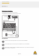
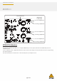
Synthesizers and Samplers MODEL D Preliminary Procedure Follow all steps in the order in which they are presented. The diagram below shows the typical connections for this procedure.
Synthesizers and Samplers MODEL D Turn down the MODEL D headphone volume knob, and connect your headphones to the MODEL D headphones output connector. Alternatively, you can monitor the MODEL D output using the main outputs and a suitable sound system and speakers. Turn on the MODEL D rear panel power switch and check that its Power LED comes on. Important: Leave the MODEL D turned on for approximately 30 minutes.
Synthesizers and Samplers MODEL D Carefully undo the 8 screws on the top panel as shown. There is no need to undo any other screws. Take care not to pull on these cables Carefully lift the top panel assembly and turn it over so the PCB is facing upwards. Be careful not to pull on the two cables from the lower side of the main PCB. As your connections to other equipment are still in place, take care not to pull out any cables or damage them.
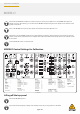
Synthesizers and Samplers MODEL D If the A-440 switch is in the ON position, you should hear the tone in your heaphones or main system if you carefully bring the headphone volume or main volume up. Now that everything is ready, inspect the bottom surface of the PCB as shown on the next page. The diagram below shows the Test Points TP1 and TP2 used in the PITCH/CV calibration. Take a look at the PCB and locate these two test points. DC Voltmeter 0.
Synthesizers and Samplers MODEL D Highest C6 Octave Adjustment Highest A5 Lowest A2 OSC3 Scale Adjustment OSC3 Range Adjustment OSC2 Scale Adjustment OSC2 Range Adjustment OSC1 Scale Adjustment OSC1 Range Adjustment PITCH CV Calibration The PITCH CV calibration procedure uses a computer MIDI utility to send a SysEx command to the MODEL D to put it into calibration mode.
Synthesizers and Samplers MODEL D Putting the MODEL D into Pitch CV Calibration Mode The following example shows the use of the popular MIDI Utility “MIDI OX” to send a SysEx message from your computer to the MODEL D to put it into PITCH CV Calibration mode. (This same procedure can be used to send any SysEx message to the MODEL D.) Run MIDI OX on your computer, and go to OPTIONS/MIDI DEVICES. Select the MODEL D as the MIDI IN and MIDI OUT.
Synthesizers and Samplers MODEL D Select "Pass SysEx" at the bottom of the Options pull down menu. (It might already be ticked, which is fine.) In the VIEW Menu, select SysEx..
Synthesizers and Samplers MODEL D In the Command Window, enter the SysEx command to be sent to the MODEL D. For PITCH Calibration, the command is: F0 00 20 32 00 7F 0E 00 00 00 F7 In the Command Window drop-down menu, select Send SysEx.
Synthesizers and Samplers MODEL D The SysEx message will be sent to the MODEL D, and it will then be in its PITCH Calibration mode. If you wanted, you can use the SAVE AS command in the Command Window drop down menu to save the SysEx message as a file on your computer for later use. Then use the LOAD command in the Command Window drop down menu to recall the SysEx message from a file on your computer.
Synthesizers and Samplers MODEL D Pitch CV Calibration continued Follow the procedure on the previous page to put the MODEL D into PITCH Calibration mode using SysEx. Make sure that the preliminary procedures shown in section 5.1 have been followed, and the MODEL D front panel controls and switches are set as directed. Set the Digital Voltmeter to measure a range below 10 VDC.S Locate the Test Points PITCH CV TP1 and TP2 on the bottom surface of the main PCB, as shown below.
Synthesizers and Samplers MODEL D Connect the positive probe of your Voltmeter to TP2. C#3 C3 D3 E3 F3 C#4 C4 D4 E4 E4 Start High Calibration. Target voltage is 6.500 Vdc D4 Start Zero Calibration. Target voltage is 0.000 Vdc C4 Start Low Calibration. Target voltage is -2.
Synthesizers and Samplers MODEL D Zero Calibration Adjustment Press D4 on the external keyboard to set the Zero calibration value. Measure the output voltage. It should read 0.000 VDC. If required, the output voltage can be adjusted to this value by pressing the following keys.
Synthesizers and Samplers MODEL D Exiting the PITCH CV Calibration Procedure When you are finished, you must press C#4 to exit the Calibration Mode and return the MODEL D to normal operation. If you want to do the other calibrations for the oscillators and octave range, follow the procedures shown on the next pages.
Synthesizers and Samplers MODEL D The diagram below shows the keyboard notes that are used in the calibrations. Only A2 and A5 are used in the Oscillator calibration, and C6 is used in the Octave calibration. Alternatively, notes may be played using a DAW with a MIDI interface connected to the MIDI IN on the MODEL D.
Synthesizers and Samplers MODEL D Repeat steps 5 and 6 above until both notes are correct in the display. This may need to be repeated several times to get right. Turn OFF the OSC1 switch. OSC 2 Scale and Range Calibration On the PCB, locate the OSC2 RANGE and OSC2 SCALE pots. Turn ON the OSC2 switch. On your external keyboard, press and hold the A5 key and adjust the OSC2 RANGE trimpot on the PCB while observing the tuner display.
Synthesizers and Samplers MODEL D On your external keyboard, press and hold the A2 key and adjust the OSC3 SCALE trimpot on the PCB while observing the tuner display. Repeat steps 17 and 18 above until both notes are correct in the display. This may need to be repeated several times to get right. Turn OFF the OSC3 switch. This completes the Oscillator Range and Scale Calibration. If you want to do the other calibrations for the octave range, follow the procedures shown on the next pages.
Synthesizers and Samplers MODEL D Turn OFF the A-440 switch. Make sure the OSC1 switch is left ON for the next calibration. OSC 2 Scale and Range Calibration On the PCB, locate the OSC2 RANGE and OSC2 SCALE pots. As set up in the previous procedure, the A-440 test tone should be off, and the OSC1 switch should be set on. Turn on the OSC2 switch. On your external keyboard, press and hold the A5 key.
Synthesizers and Samplers MODEL D On your external keyboard, press and hold the A5 key. Listen carefully to the combination of OSC1 and OSC3, and adjust the OSC3 RANGE trimpot on the PCB for zero beats between them. On your external keyboard, press and hold the A2 key. Listen carefully to the combination of OSC1 and OSC3, and adjust the OSC3 SCALE trimpot on the PCB for zero beats between them. Repeat steps 18 and 19 above until there are zero beats for either note.
Synthesizers and Samplers MODEL D On the PCB, locate the OSC SW pot Highest C6 Octave Adjustment Highest A5 Lowest A2 OSC3 Scale Adjustment OSC3 Range Adjustment OSC2 Scale Adjustment OSC2 Range Adjustment OSC1 Scale Adjustment OSC1 Range Adjustment Turn all the Octave RANGE knobs to the 2' position in the OSCILLATOR BANK section.
Synthesizers and Samplers MODEL D Turn on the front panel OSC2 VOLUME switch in the MIXER section. (OSC1 is already on, OSC1 and 2 Volumes are up). OSC1 ON OSC1 Max OSC2 Max OSC2 ON On your external keyboard, press and hold the C6 key. You should hear both OSC1 and OSC2. Adjust the headphone volume or main volume as required. Listen carefully, and adjust the front panel OSCILLATOR-2 Tune knob until there are zero beats between OSC1 and OSC2.
Synthesizers and Samplers MODEL D Turn the front panel OSC2 Octave RANGE knob to the 8' position. RANGE 8’ On the PCB, locate the OSC2 RANGE and OSC2 SCALE pots. C6 Octave Calibration Oscillator Calibration A2 Low Value A5 High Value Listen carefully, and adjust the OSC SW trimpot on the PCB, for zero beats between OSC1 (Range=2') and OSC2 (Range=8').