User Manual iNUKE NU6000DSP/NU3000DSP/NU1000DSP Ultra-Lightweight, High-Density 6000/3000/1000-Watt Power Amplifier with DSP Control and USB Interface
iNUKE NU6000DSP/NU3000DSP/NU1000DSP User Manual Table of Contents Thank you........................................................................ 2 Important Safety Instructions....................................... 3 Legal Disclaimer.............................................................. 3 Limited Warranty............................................................ 3 1. Introduction................................................................ 5 1.1 Before you get started...................
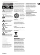
iNUKE NU6000DSP/NU3000DSP/NU1000DSP User Manual ImportantSafety Safety Important Instructions Instructions Terminals marked with this symbol carry electrical current of sufficient magnitude to constitute risk of electric shock. Use only high-quality professional speaker cables with ¼" TS or twist-locking plugs pre-installed. All other installation or modification should be performed only by qualified personnel.
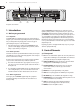
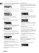
iNUKE NU6000DSP/NU3000DSP/NU1000DSP User Manual (1) (3) (2) (4) (5) (7) (6) (8) (9) Front panel control elements 1. Introduction 1.1 Before you get started 1.1.1 Shipment Your iNUKE amplifier was carefully packed at the factory, and the packaging is designed to protect the unit from rough handling. Nevertheless, we recommend that you carefully examine the packaging and its contents for any signs of physical damage that may have occurred during transit.
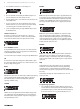
iNUKE NU6000DSP/NU3000DSP/NU1000DSP User Manual (10) (11) (12) (13) (14) Rear panel control elements (NU6000DSP shown) 2.2 Rear panel (10) BREAKER (automated fuse, NU6000DSP only). After eliminating the cause of faulty operation, simply depress the BREAKER and power up the unit again. The BREAKER acts in place of common discardable fuses. (11) POWER SOURCE jack accepts the included IEC power cable. (12) VENTILATION FAN speed adjusts automatically to ensure trouble-free operation.
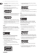
iNUKE NU6000DSP/NU3000DSP/NU1000DSP User Manual 2. Press the SELECT encoder knob to access the DSP’s internal Preset list on the next sub-screen. The correct sub-screen will display the EDIT TITLE and SAVE PRESET options on the right-hand side of the screen. SETUP 2/4: Panel Lock The Panel Lock function uses a 4-character alphanumeric access code to lock the front panel controls and prevent unauthorized changes to DSP settings.
iNUKE NU6000DSP/NU3000DSP/NU1000DSP User Manual 2. Press the SELECT encoder knob to access the editing screen. BIAMP1 3. Choose the backwards arrow by turning the SELECT knob and press it to delete the existing characters of the current preset name. BIAMP1 mode splits the Channel A input signal at a programmable frequency point, and then routes the resulting high and low frequency signals through a parallel chain of DSP modules with independent equalization, signal delay, and limiter settings.
iNUKE NU6000DSP/NU3000DSP/NU1000DSP User Manual 2. Press the SELECT encoder knob to enter the parameter screens for your chosen EQ band. 5. Set the filter thresholds for high-pass (HPfreq) and low-pass (LPfreq) by rotating the SELECT encoder knob. 3. Press the UP / DOWN arrow keys to switch between parameters. The chosen parameter will appear highlighted. 6. Set the filter’s overall signal gain (Gain) by rotating the SELECT encoder knob. 4. Rotate the SELECT encoder knob to change parameter values.
iNUKE NU6000DSP/NU3000DSP/NU1000DSP User Manual 10. Adjust attack (Atime) and release (Rtime) to your preferred values. 3.3 BEHRINGER Amp Remote Software 11. Press the SELECT encoder when finished to return to the top-level DEQ screen. DELAY The DELAY DSP module digitally slows the final signal output from the amplifier by a programmable amount (expressed as either distance or time).
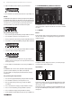
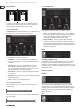
iNUKE NU6000DSP/NU3000DSP/NU1000DSP User Manual Output Meters 3.3.4 Configuration The output meters show the signal level at the end of the DSP signal chain, following the Limit module. If the signal activates the limiter, the red Limit indicator will light over the channel experiencing an overload. 3.3.2 Function Tabs The BEHRINGER Amp Remote window allows the user to access DSP functions via embedded tabs accessible near the top of the software window.
iNUKE NU6000DSP/NU3000DSP/NU1000DSP User Manual Stereo mode routes the signal from both the A and B inputs through a single series of DSP modules. Each DSP module processes both the A and B signals with identical, linked settings. The linked Delay and Limit parameters can be controlled from Stereo mode’s consolidated Channel A+B control window (which displays automatically when Stereo mode is selected).
iNUKE NU6000DSP/NU3000DSP/NU1000DSP User Manual 3. Choose a Hold value either by rotating the Hold virtual knob or by entering a value (in milliseconds) into the matching text box below the knob. Filter/Crossover Control View 4. Choose a Release value either by rotating the Release virtual knob or by entering a value (in milliseconds) into the matching text box below the knob. 3.3.
iNUKE NU6000DSP/NU3000DSP/NU1000DSP User Manual • Frequency Curve—displays the filter curves in visual form, and allows click-and-drag manipulation of EQ frequencies and gain. The Frequency Curve and Control View interact with each other and simultaneously shift as you change parameters in either view. Parametric EQ Control View The Control View of the Parametric EQ tab contains virtual knob controls for Gain, Frequency, Quality (parametric EQ only).
iNUKE NU6000DSP/NU3000DSP/NU1000DSP User Manual Adjusting dynamic EQ gain via click-and-drag 1. Click and hold on the numbered box at the top of the desired dynamic EQ band frequency line. 6. Program your desired ratio by selecting from the Ratio pulldown menu. Similar to a compressor, higher ratio values yield a more intense equalization effect. 2. Move the cursor vertically up or down the frequency line to the desired gain level. 7.
iNUKE NU6000DSP/NU3000DSP/NU1000DSP User Manual 2. Click on the Recall button in the upper left of the Amp Presets section. The selected preset’s name will appear in the text box next to the Recall button. All settings contained in the preset will automatically deploy. Renaming an amplifier Saving a preset to the amp’s internal memory 2. Click on the Rename Amp virtual button. The new amplifier name will appear in the Amp Name column of the amplifier list. 1.
iNUKE NU6000DSP/NU3000DSP/NU1000DSP User Manual Programming BEHRINGER Amp Remote Software for bi-amping Again, matching parameters will automatically appear in both filter’s Control View settings. 1. Select the Configuration tab. 9. Set the crossover frequency by using any of these three methods: 2. Choose the Bi-Amp 2 signal path in the Configuration tab. A confirmation window will pop up. a) Rotate the Low Pass 2 or High Pass 3 virtual Freq knobs in the Control View.
iNUKE NU6000DSP/NU3000DSP/NU1000DSP User Manual 5. Installation Unbalanced ¼" TS connector 5.1 Rack mounting strain relief clamp sleeve Your iNUKE amplifier fits into a 19" rack and requires two rack units. Install into the rack using four attaching screws and washers for the front panel. Reinforce the back panel, especially if you will be taking the iNUKE on the road. Make sure enough cool air reaches the rack, especially when other rack equipment emanates a lot of heat.
iNUKE NU6000DSP/NU3000DSP/NU1000DSP User Manual 6.
iNUKE NU6000DSP/NU3000DSP/NU1000DSP User Manual NU3000DSP Connectors Output Power Maximum Output Power Stereo 8 Ω per channel, stereo 440 W 4 Ω per channel, stereo 820 W 2 Ω per channel, stereo 1520 W Bridged mono 8Ω 1520 W 4Ω 3000 W System Controls Front Power switch, Gain controls (channels A and B) DSP section rotary push-encoder, Buttons for Process, Setup, Up/Down, Exit Indicators Power Amber backlit illuminated gain controls Limit (per channel) 0 dB, full scale Signal (per chan
iNUKE NU6000DSP/NU3000DSP/NU1000DSP User Manual NU1000DSP Connectors Output Power Maximum Output Power Stereo 8 Ω per channel, stereo 160 W 4 Ω per channel, stereo 310 W 2 Ω per channel, stereo 530 W Bridged mono 8Ω 620 W 4Ω 1050 W System Controls Front Power switch, Gain controls (channels A and B) DSP section rotary push-encoder, Buttons for Process, Setup, Up/Down, Exit Indicators Power Amber backlit illuminated gain controls Limit (per channel) 0 dB, full scale Signal (per channe
iNUKE NU6000DSP/NU3000DSP/NU1000DSP User Manual FEDERAL COMMUNICATIONS COMMISSION COMPLIANCE INFORMATION iNUKE NU6000DSP/NU3000DSP/ NU1000DSP Responsible Party Name: MUSIC Group Services US Inc. Address: 18912 North Creek Parkway, Suite 200 Bothell, WA 98011, USA Phone/Fax No.
We Hear You