Version 2.3 June 2002 www.behringer.
DENOISER SNR2000 SAFETY INSTRUCTIONS CAUTION: To reduce the risk of electrical shock, do not remove the cover (or back). No user serviceable parts inside; refer servicing to qualified personnel. WARNING: To reduce the risk of fire or electrical shock, do not expose this appliance to rain or moisture. This symbol, wherever it appears, alerts you to the presence of uninsulated dangerous voltage inside the enclosure voltage that may be sufficient to constitute a risk of shock.
DENOISER SNR2000 FOREWORD Dear Customer, Welcome to the team of DENOISER users and thank you very much for expressing your confidence in BEHRINGER products by purchasing the SNR2000. It is one of my most pleasant tasks to write this letter to you, because it is the culmination of many months of hard work delivered by our engineering team to reach a very ambitious goal: making an outstanding device that will become a standard tool used by studios and P.A. companies.
DENOISER SNR2000 DENOISER® Professional and all-purpose single-ended noise reduction system SNR2000 s TAC (Transient Attack Control) dynamic filters respond accurately to signals with fast attacks s Auto-filter circuitry for automatic sliding filters s IRC (Interactive Ratio Control) downward expander for inaudible noise reduction during signal pauses s Accurate gain reduction and cut-off frequency meters s Dual mono or true stereo couple function s Servo-balanced inputs and outputs on XLR an
DENOISER SNR2000 TABLE OF CONTENTS 1. INTRODUCTION .....................................................................................................................6 1.1 The design concept ......................................................................................................................... 1.2 Before you begin ............................................................................................................................. 1.3 Control elements ............................
DENOISER SNR2000 1. INTRODUCTION Thank you very much for expressing your confidence in BEHRINGER products by purchasing the BEHRINGER DENOISER SNR2000. Electrical noise is still one of the most unpleasant problems in the field of electro-acoustics. The basic noise produced by a single unit is not considered to be annoying. The combination of several instruments, effects devices and tape machines, however, results in a drastic increase in noise level. This requires the use of a noise reduction system.
DENOISER SNR2000 1.2 Before you begin Your DENOISER was carefully packed in the factory and the packaging is designed to protect the unit from rough handling. Nevertheless, we recommend that you carefully examine the packaging and its contents for any signs of physical damage, which may have occurred during transit. + If the unit is damaged, please do not return it to BEHRINGER, but notify your dealer and the shipping company immediately, otherwise claims for damage or replacement may not be granted.
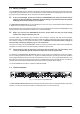
DENOISER SNR2000 1.3.1 Front panel Fig. 1.2: Front panel control elements 1 The IN/OUT switch activates the relay and, consequently, the corresponding channel. The unit is bypassed when the switch is not depressed. 2 By depressing the COUPLE switch you will tie channel 1 and 2 together for stereo tracking. + If using the COUPLE switch, it is recommended that all controls be set identically on both channels to ensure proper tracking. 3 The EXPANDER IN/OUT switch activates the expander section.
DENOISER SNR2000 15 FUSE HOLDER / VOLTAGE SELECTOR. Please make sure that your local voltage matches the voltage indicated on the unit, before you attempt to connect and operate the DENOISER. Blown fuses may only be replaced by fuses of the same type and rating. Some models allow for inserting the fuse holder in two different positions, in order to switch over from 230 V to 115 V operation, and vice versa.
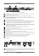
DENOISER SNR2000 Fig. 2.1: Operation of the dynamic filter With a low-frequency input signal present, the dynamic filter will reduce any mid or high-band noise as well as any disturbing noise tails. If the input signal is dominated by high-frequency components, however, the dynamic filter will open to its full extent to let the signal pass, maintaining high-frequency information. 2.
DENOISER SNR2000 Fig. 2.2: Comparing the BEHRINGER TAC filter circuitry and the conventional RMS characteristic curve 2.2.1 SENSITIVITY control This control determines the sensitivity of the filter. If the input level exceeds the value adjusted with the SENSITIVITY control, the dynamic filter begins to open. If the adjusted value is, for example, -30 dBu, highfrequency signals with a level above -30 dBu cause the filter to open.
DENOISER SNR2000 2.2.4 AUTO switch The AUTO switch allows to automatically control release time and cut off frequency of the TAC filter. Thus, by depressing the AUTO switch, the RELEASE and CUT OFF controls are deactivated. Release time and cut off frequency of the filter are now automatically derived from the input signal. Generally, good results will be achieved with the AUTO function. However, with complex sound sources e.g.
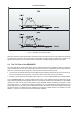
DENOISER SNR2000 Fig. 2.3: The function of an expander 2.4 The IRC expander of the DENOISER The response characteristics of conventional expanders tend to cut the signal abruptly and the result is generally unacceptable, since the effect is clearly audible. Inaudible expansion, however, requires a gentle Soft Knee characteristic due to a continuous transition of the straight lines at the threshold. A newly developed IRC (Interactive Ratio Control) expander has been integrated into the DENOISER.
DENOISER SNR2000 2.4.1 THRESHOLD control The THRESHOLD control of the expander defines the operating level. It stretches across a very wide range and therefore applies to all working levels. Input levels above the adjusted threshold point do not experience any change. However, if the level falls below the threshold the dynamic process is active. For example, if the THRESHOLD control was set at 0 dBu and the input signal drops below 0 dBu, downward expansion will begin.
DENOISER SNR2000 2.5 The COUPLE function The couple switch links channel 1 and channel 2. This includes each channels expander detection and filter detection circuits. Although this allows the two channels to track each other for stereo applications, it should be pointed out that this is not a master/slave setup, but rather a link and for true stereo tracking it is necessary to set both channels controls identically.
DENOISER SNR2000 We recommend the following control settings: Controls Settings IN/OUT switch IN EXPANDER switch IN THRESHOLD control -50 dBu RELEASE control 2 seconds RATIO control 3:1 FILTER switch IN SENSITIVITY switch -30 dBu AUTO switch IN Tab. 3.2: Initial settings of the DENOISER 3.2 Studio applications 3.2.1 Noise reduction during playback For this standard application, the DENOISER is inserted after the master or multitrack machine, i.e. between tape machine and mixer (or amplifier).
DENOISER SNR2000 Fig. 3.2: Noise reduction during recording If the mixer features a line level insert (either pre or post equalizer), the DENOISER should be inserted here. Fig. 3.3: Noise reduction using the line insert 3.2.3 Reducing noise on subgroups, monitor and effects buses For this application there are several options: 1. If your mixer features subgroup inserts, you can reduce noise in subgroups separately. 2.
DENOISER SNR2000 Fig. 3.4: Noise reduction in the effects bus 3.2.4 Noise reduction for effects devices Effects devices such as flangers, phasers, distortion or chorus units, delay and reverb devices, compressors, equalizers, exciters, etc. can considerably increase the overall noise level. The DENOISER will also be useful here. Simply insert the unit after the effects device that causes noise problems. If there are several devices, insert the DENOISER as the last unit in the signal chain. 3.2.
DENOISER SNR2000 Fig. 3.6: Noise reduction on keyboards + Please note that low level signal sources such as guitars must be pre-amplified beforehand, as the BEHRINGER DENOISER only processes line level signals (-10 dBV to +10 dBu). 3.2.7 Reducing noise in P.A. systems The noise produced by P.A. systems is particularly annoying. Hum induced in the microphone cables combined with high gain settings results in a drastic increase of noise. The DENOISER can solve these problems, too.
DENOISER SNR2000 Fig. 3.8: Noise reduction in Hi-Fi systems The BEHRINGER DENOISER can be used for: s disc and tape recordings s video and audio cassette playback purposes s TV reception s radio reception 4. TECHNICAL BACKGROUND 4.1 What are audio dynamics? A remarkable feature of the human ear is that it can detect the widest range of amplitude changesfrom the slightest whisper to the deafening roar of a jet-plane.
DENOISER SNR2000 The usable dynamic range of electro-acoustic equipment is limited to both the low end and the high end. The thermal noise of the electrons in the components results in an audible basic noise floor and thus represents the bottom limit of the transmission range. The upper limit is determined by the levels of the internal operating voltages; if they are exceeded, audible signal distortion is the result.
DENOISER SNR2000 The noise gate is the simplest form of an expander: in contrast to the expander, which continuously attenuates a signal below the threshold, the noise gate cuts off the signal abruptly. In most applications this method is not very useful, since the on/off transition is too drastic. The onset of a simple gate function appears very obvious and unnatural. To achieve inaudible processing of the program material, it is necessary to control the signals envelope parameters. 4.
DENOISER SNR2000 4.7 The single-ended principle In contrast to conventional noise reduction systems using compressors and expanders, the DENOISER is purely a single-ended system. Single-ended means that the noise reduction system is not based on a process combining both record and playback (encoding and decoding), but is simply inserted into the signal chain after the signal that is going to benefit from noise reduction.
DENOISER SNR2000 Fig. 5.1: Different plug types 6. SPECIFICATIONS Analog inputs Connectors Type Impedance Nominal operating level Max. input level XLR and 1/4" TRS RF filtered, servo balanced input 80 kOhms balanced -10 dBV to +4 dBu (switchable) +20 dBu balanced and unbalanced Analog outputs Connectors Type Impedance Max. output level XLR and 1/4" TRS Electronically servo-balanced output stage (optional transformer-balanced) 40 Ohms balanced or unbalanced +26 dBm balanced, +20 dBm unbalanced 24 6.
DENOISER SNR2000 System specifications Bandwidth Noise THD Crosstalk 5 Hz to 100 kHz, +0/-3 dB > 104 dBu, fully off 0.02% typ. @ +4 dBu, 1 kHz, Gain 1 < -85 dBu Expander section Threshold Release Ratio variable (-40 to +20 dBu) variable (0.05 to 6 seconds) variable (1:1 to 1:6) Filter section Sensitivity Release Cut-off variable (-50 to +10 dBu) variable (0.06 to 1.
DENOISER SNR2000 7. WARRANTY § 1 WARRANTY CARD/ONLINE REGISTRATION To be protected by the extended warranty, the buyer must complete and return the enclosed warranty card within 14 days of the date of purchase to BEHRINGER Spezielle Studiotechnik GmbH, in accordance with the conditions stipulated in § 3. Failure to return the card in due time (date as per postmark) will void any extended warranty claims.