Bedienungsanleitung Version 1.2 January 1999 ULTRAMATCH SRC2000 User´s Manual www.behringer.
EG-Declaration of Conformity Spezielle Studiotechnik GmbH acc.
SAFETY INSTRUCTIONS CAUTION: To reduce the risk of electrical shock, do not remove the cover (or back). No user serviceable parts inside; refer servicing to qualified personnel. WARNING: To reduce the risk of fire or electrical shock, do not expose this appliance to rain or moisture. This symbol, wherever it appears, alerts you to the presence of uninsulated dangerous voltage inside the enclosure - voltage that may be sufficient to constitute a risk of shock.
ULTRAMATCH Provides virtually all possible digital format conversions of professional and consumer modes, AES/EBU, SPDIF coaxial or optical SRC2000 s Accepts sampling frequencies from 25 kHz to 60 kHz s Selectable input (XLR, RCA, optical) s Converts into output frequencies 44,1 kHz or 32 kHz s The output signal format can be specified - No incompatibilities s All outputs (XLR, RCA, optical) are concurrently active (splitter, signal distribution) s Enables manipulation of Emphasis and copy pro
FOREWORD Dear Customer, Welcome to the BEHRINGER ULTRAMATCH and thank you for placing your trust in BEHRINGER products. My most pleasant task is to write this letter to you, because it is the culmination of many months of hard work for our engineering team. Our daily objective is to be focused on you, the musician and sound engineer, and with that focus in mind, it drives us to reach a goal which is unique, and is the backbone of the BEHRINGER philosophy.
TABLE OF CONTENT 1. INTRODUCTION ...................................................................................................................... 7 1.1 Some Words on Digital Sample Rate Conversion ........................................................................... 7 1.2 The AES/EBU and SPDIF Standards .............................................................................................. 7 2. THE CONCEPT ..................................................................................
1. INTRODUCTION BEHRINGER ULTRAMATCH is an essential tool for modern recording studios. The importance of digital technology has grown immensely during the past years in home-recording as well as in semi-professional and professional studios. More and more operations are executed on the digital level. As a result, sound engineers and musicians are confronted with a multitude of new connectors, signal leads, and changed standards.
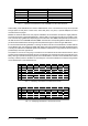
Type Connection Mode of operation Impedance Level Clock Accuracy Jitter AES / EBU XLR Balanced 110 Ohms 0.2 V to 5 V pp not defined ± 20 ns IEC 958 (SPDIF) RCA / Optical Unbalanced 75 Ohms 0.2 V to 0.5 V pp I: ± 50 ppm II: 0,1 % III: Variable Pitch not defined Tab. 1.1: Important characteristics of the AES/EBU and IEC 958 standards. Unfortunately, these standards soon became watered-down, since a lot of devices simply did not provide enough space for XLR jacks.
2. THE CONCEPT The BEHRINGER ULTRAMATCH is an especially flexible device meeting all the requirements of digital applications. Compared to most conventional sample rate converters, the ULTRAMATCH offers much more than mere sample rate conversion, due not only to various options for signal manipulation but also the provision of the complete input and output interface. The front panel of the ULTRAMATCH is strictly functional and has a user-oriented design.
+ Note: The ADAT multi-track format is not supported by the ULTRAMATCH and is therefore neither passed through nor converted (ADAT is a registrated trademark of Alesis Corp.). 2.2.4 Wordclock (BNC) The BNC jack on the rear panel allows to connect the ULTRAMATCH to a wordclock source for synchronization purposes (s. a. 3.3.4). Wordclock signals are normally distributed in network technology, i. e. they are passed through with BNC-T adapters and terminated with appropriate resistor elements.
3. INSTALLATION Your BEHRINGER ULTRAMATCH was carefully packed in the factory and the packaging was designed to protect the unit from rough handling. Nevertheless, we recommend that you carefully examine the packaging and its contents for any signs of physical damage, which may have occurred in transit. + If the unit is damaged, please do not return it to us, but notify your dealer and the shipping company immediately, otherwise claims for damage or replacement may not be granted.
unit A output AES/EBU 2 ULTRAMATCH input signal flow 1 1 3 cable shield 2 3 Fig.3.1: Balanced Connections (AES / EBU) to the ULTRAMATCH 3.3.2 Unbalanced Coaxial Connections (SPDIF) The figure below shows how to connect the unbalanced inputs and outputs correctly by means of RCA cables. Basically, the connections are identical to unbalanced audio connections in stereo systems, for example when connecting a CD player to an amplifier.
unit A optical output S/PDIF signal flow ULTRAMATCH optical input E Fig. 3.3: Optical Connection via TOSLINK (SPDIF) to the ULTRAMATCH 3.3.4 Wordclock The figure below shows how to connect the unbalanced wordclock input correctly. Basically, the connection is identical to those used in computer network wiring. Actually, the necessary accessories (T-adapters, terminal resistors) are available at most computer dealers. Usually, ready-made BNC cables are used for the connection.
3.3.5 Connections with Adapters In some cases, it may be appropriate to connect the inputs and outputs of the ULTRAMATCH to other devices by means of adapter units. For example, if you want to connect two DAT recorders to the ULTRAMATCH at the same time, and each of these recorders features only an SPDIF interface (RCA), you can easily connect one of these recorders to the ULTRAMATCH by means of an RCA-XLR adapter. The figure below shows e. g. the correct wiring of the adapter cables for input connection.
4. CONTROLS AND FUNCTIONS 4.1 Front Panel E Fig. 4.1: Controls on the ULTRAMATCHs Front Panel 1 INPUT Section. Each of the three switches to the left activates the respective input. 2 LED-Display. The clearly organized display, located in the center of the front panel, indicates the status of the input signal, the selected synchronization type, and the status of the output signal. 3 OUTPUT Section.
4.1.2 LED-Display 7 9 8 10 12 13 15 17 11 14 16 18 19 20 Fig. 4.3: The Indicators of the LED Display Section 7 SPDIF Indicator. When the SPDIF input is activated, this LED is lit. 8 AES/EBU Indicator. When the AES/EBU input is activated, this LED is lit. 9 OPTICAL Indicator. When the optical input is activated, this LED is lit. 10 ERROR Indicator. When the input signal is faulty, this LED is lit. It indicates several malfunctions such as No Lock, Parity, CRC, Valid, etc.
4.1.3 Output Section 21 22 23 24 E Fig. 4.4: Controls of the Output Section 21 SYNC Switch. Pressing this switch allows you to synchronize the ULTRAMATCH from an external source connected to the wordclock input on the rear panel. 22 SAMPLE FREQ Switch. Set the output sample rate to 44.1 kHz or 32 kHz with this switch. + If the mode EXTERN SYNC has been selected, set this switch to the sample rate of the wordclock signal to assign the correct sample rate information (32 kHz or 44.
5. MODE OF OPERATION The ULTRAMATCH is an all-purpose device for modern recording studios. It provides not only sample rate conversion but also format and standard conversion, and additionally allows you to manipulate part of the information transmitted with the audio signal. The ULTRAMATCH features no bypass mode, since input and output signal are practically identical if the same sample rate is applied to both input and output.
6. APPLICATIONS The universal full-function concept of the ULTRAMATCH allows plenty of applications. It turns out to be an ultimate tool, providing useful solutions for almost any problem. The power of the ULTRAMATCH is accessible via a simple and intelligible user-interface, allowing quick and easy operation. 6.1 Sample Rate Conversion No matter what kind of material is received, the ULTRAMATCH converts it to a standard format.
the model collapses! The mixing console can only lock to one master source, the audio data received from the other device would be processed wrongly since no synchronization data are available. The only thing one would hear is interference. The synchronization requirements in a digital studio can be met by connecting a central sync master. For instance, the mixing console may act as master and controls all other devices by transmitting a reference code (word clock).
to the transmitted rate and automatically cancels operation. With the ULTRAMATCH, such restrictions are history. Correct operation is provided not only for a limited range around the selected sample rate but for any sample rate between 25 kHz and 60 kHz. Moreover, the signal transmitted by the ULTRAMATCH is always synchronized to a correct rate of 44.1 kHz or 32 kHz.
can be solved that were not known to the engineers during the development process. Digital media such as Mini Disc (MD) or DCC (Digital Compact Cassette) have spread widely during the past years. However, such devices are not able to record via their digital input with a sample rate of 32 kHz. Due to that, it is not possible to record digital radio broadcasts directly; a D/A conversion with subsequent A/D conversion seems to be unavoidable.
7. SPECIFICATIONS Digital Input 1 Type Standard Impedance Nominal Input Level XLR, transformer-balanced AES/EBU 110 Ohm 0.2 V ~ 10 V peak-to-peak Digital Input 2 Type Standard Impedance Nominal Input Level RCA, transformer-balanced SPDIF 75 Ohm 0.
Dimensions & Weight Dimensions Weight including package 1 3/4 (44.5 mm) x 19 (482.6 mm) x 7 1/2 (190.5 mm) 2 kg 3.2 kg BEHRINGER is constantly striving to maintain the highest professional standards. As a result of these efforts, modifications may be made from time to time to existing products without prior notice. Specifications and appearance may differ from those listed or shown. 24 7.
8. WARRANTY § 1 WARRANTY CARD To be protected by this warranty, the buyer must complete and return the enclosed warranty card (signed/stamped by retail dealer) within 14 days of the date of purchase to BEHRINGER INTERNATIONAL (address see § 3). Failure to return the card in due time (date as per postmark) will void any extended warranty claims. ship. The warranty does not cover any such modification/adaptation, irrespective of whether it was carried out properly or not.