User Manual SUPER-X PRO CX3400 High-Precision Stereo 2-Way/3-Way/Mono 4-Way Crossover with Limiters, Adjustable Time Delays and CD Horn Correction
SUPER-X PRO CX3400 User Manual Table of Contents Thank you........................................................................ 2 1. Introduction................................................................ 5 1.1 Multi-way speaker systems.............................................. 5 1.2 SUPER-X PRO: the high-end frequency crossover................................................................... 5 2. The Design Concept................................................... 5 2.1 Before you begin.
SUPER-X PRO CX3400 User Manual Important Safety Instructions Terminals marked with this symbol carry electrical current of sufficient magnitude to constitute risk of electric shock. Use only high-quality commercially-available speaker cables with ¼" TS plugs pre-installed. All other installation or modification should be performed only by qualified personnel.
SUPER-X PRO CX3400 User Manual “Support” at behringer.com. If your country is not listed, please check if your problem can be dealt with by our “Online Support” which may also be found under “Support” at behringer.com. Alternatively, please submit an online warranty claim at behringer.com BEFORE returning the product. All inquiries must be accompanied by a description of the problem and the serial number of the product.
SUPER-X PRO CX3400 User Manual 1. Introduction 2. The Design Concept This manual first describes the terminology used, so that you can fully understand the CX3400 and its functions. Please read the manual carefully and keep it for future reference. The philosophy behind BEHRINGER products guarantees a no-compromise circuit design and employs the best choice of components. The operational amplifiers NJM4580 which are used in the SUPER-X PRO, are exceptional.
SUPER-X PRO CX3400 User Manual Fig. 2.1: The front panel of the SUPER-X PRO 2.3 Control elements Since the SUPER-X PRO boasts a variety of features, we highlighted the active control elements in the following illustrations. On the unit itself, these active elements are equipped with light-emitting diodes, helping you to keep track of your settings even under poor lighting conditions. Additionally, all buttons on the front panel are backlit when activated.
SUPER-X PRO CX3400 User Manual (1) (2) (3) (5) (6) (8) (9) (10) (12) (13) (14) (15) Fig. 2.4: Active control elements on the rear panel of the SUPER-X PRO for 2-way stereo operation (1) Use the enclosed power cord to connect the unit to the mains. (2) FUSE HOLDER / VOLTAGE SELECTOR. Please make sure that your local voltage matches the voltage indicated on the unit, before you attempt to connect and operate the CX3400.
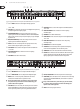
SUPER-X PRO CX3400 User Manual (7) (10) (13) (1) (4) (5) (6) (9) (12) (15) (16) (2) (3) (8) (11) (14) (30) (31) Fig. 2.6: Active control elements on the front panel of the SUPER-X PRO for stereo 3-way operation (1) and (16) INPUT control. This control adjusts the input gain from +12 to -12 dB. (2) LOW CUT button. This button activates the 25 Hz highpass filter protecting the woofers against low-frequency signals. (3) LOW/MID XOVER FREQ. control.
SUPER-X PRO CX3400 User Manual 2.3.3 Mono 4-way operation (6) LOW OUTPUT control. Controls the output level of the Low band from +6 to -6 dB. First, activate mono 4-way mode by means of the two MODE buttons on the rear panel. The MONO-LED on the front panel, above the LOW CUT button in channel 1, lights up. (7) LOW PHASE INVERT button. This button reverses the polarity of the Low output. (8) LOW MUTE button. Mutes the Low band. (9) LOW-MID OUTPUT control.
SUPER-X PRO CX3400 User Manual (3) (4) (8) (11) (12) (13) (14) Fig. 2.10: Active control elements on the rear panel of the SUPER-X PRO for mono 4-way operation (3) HIGH OUTPUT connector. Output for the High band signal. (4) HIGH-MID OUTPUT connector. Output for the High-Mid band signal. 3.1.2 Generator/Analyzer (8) MODE button. In mono 4-way mode, the right button must be pressed. Please observe the labels on the rear panel of the unit.
SUPER-X PRO CX3400 User Manual 3.4 Setting the crossover frequencies The use of extremely high-grade potentiometers made it unnecessary to install fixed-frequency plug-in modules. Thus, you have a wide range of setting options available that even more expensive crossover networks hardly give you. The CX3400 works in two specific frequency ranges: 44 though 930 Hz and 440 Hz through 9.3 kHz. The Linkwitz-Riley filters employed in the SUPER-X PRO feature a slope of 24 dB/octave.
SUPER-X PRO CX3400 User Manual Problems will be encountered only with unconventional setups (e.g. when the woofers are placed underneath the stage, while the midrange/tweeter systems are flown above it) or when long woofer horns are used. The latter are the subject of the following discussion. First, measure the horn length. In the case of folded woofer horns this is anything but easy.
SUPER-X PRO CX3400 User Manual 4. Installation Your SUPER-X PRO CX3400 was carefully packed in the factory and the packaging was designed to protect the unit from rough handling. Nevertheless, we recommend that you carefully examine the packaging and its contents for any signs of physical damage, which may have occurred in transit.
SUPER-X PRO CX3400 User Manual Unbalanced ¼" TS connector Balanced use with XLR connectors strain relief clamp sleeve tip 2 1 3 input sleeve (ground/shield) 1 = ground/shield 2 = hot (+ve) 3 = cold (-ve) 1 tip (signal) 2 3 output For unbalanced use, pin 1 and pin 3 have to be bridged Balanced ¼" TRS connector strain relief clamp sleeve ring tip sleeve ground/shield ring cold (-ve) tip hot (+ve) For connection of balanced and unbalanced plugs, ring and sleeve have to be bridged at the stereo pl
SUPER-X PRO CX3400 User Manual 5. Specifications Input Function Switches Connectors XLR Type Electronically servo-balanced, RF filtered Impedance Balanced >50 kOhms, unbalanced >25 kOhms Max.
We Hear You