
User's Manual


5 ULTR APATCH PRO PX300 0 User Manual
1. Introduction
What are patchbays for? A patchbay allows you to patch
(or interconnect) the audio signals of most components in your system from a
central point and send them to other units, making your entire cabling more
organized and better suited for professional work. If you want to use your
studio as eectively as possible, it is recommended that you use a complete
patchbay wiring scheme—even smaller studios will benet from a less complex
patchbay conguration.
2. Patchbay Organization
The ULTRAPATCH PRO PX3000 has two rows (A and B) of 24 balanced ¼" jacks on
the 1 HU 19" front rack panel. The same number and conguration of balanced
¼" jacks are on the rear panel. These jacks are grouped in fours (A and B from
the front with the corresponding A and B on the rear) to form the 24 channels.
Each channel has a switch on the top of the unit that allows you to select
the operating mode for each channel: NORMAL (normalized), HALF NORMAL
(half normalized) and THRU (through-connected). Connect your audio equipment
to the rear jacks, then you can easily interconnect your equipment or recongure
your setup using short patch cables plugged into the jacks on the front panel.
Of course, you can also use unbalanced cables.
◊ Basic rule: on a patchbay the upper jacks are always outputs, the lower
jacks inputs.
When using several patchbays, plan the layout of your standard conguration to
avoid a tangle of cables. Arrange the channels one below the other in such a way
that you could connect several patchbays without having to cross connect or span
great distances.
2.1 NORMAL mode
REAR FRONT REAR FRONT REAR FRONT REAR FRONT
A
B
A
B
A
B
A
B
(1) (2) (3) (4)
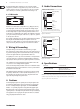
In NORMAL mode the rear A & B jacks of the channel are connected together
(pos (1) ). The connection between the rear jacks is disabled when you insert a
cable into jack A or B on the front panel (pos. (2)) and (3) ).
In the example above, top-row channels 1 to 4 are from the outputs of a
keyboard and a MIDI sound module. They are connected, in this example
conguration, to input channels 1 to 4 on the mixer.
Channels 5 and 6 are from the subgroup outputs of a mixer and are connected,
in this example conguration, to the inputs of a computer audio card.
Audio sequencer software records the music signals directly onto the hard disk
of the computer. Channels 7 and 8 connect the soundcard outputs to the 2-track
inputs of the mixer. Since the rear-panel jacks are connected together in the
NORMAL mode (pos. (1) ), the subgroup signals can be recorded directly onto
the PC and played back via the 2-track input of the mixer (playback/monitoring),
without a single patch cable having to be plugged in! In this way, you can build
up a basic conguration for your studio, which can be easily modied by simply
patching signals via the front-panel jacks (pos. (2) ) or by feeding in external
signals via patch cables (pos. (3) ). You could, for example, connect the keyboard
signal to channels 3 and 4 by patching 1A to 3B, and 2A to 4B. So, before wiring
your studio, it is advisable to identify the connections that will be used most
frequently and set them up, as your basic conguration, one above the other
on the patchbay. Then you will have a clear overview of all connections and still
be exible.
2.2 HALF NORMAL mode
In HALF NORMAL mode, the rear A & B jacks of the channel are connected
togeth er (po s. (1) ). Unlike NORMAL mode, the connection between the
rear-panel jacks is not disabled when a ¼" plug is inserted into jack A on the
front panel (pos. (2) ). This allows you to take the signal from a mixers channel
strip in parallel—without interrupting the signal path on the channel strip.
LikeNORMAL mode, the connection between the rear-panel jacks is disabled
when a ¼" plug is inserted into jack B on the front panel (pos. (3) ). When ¼"
plugs are inserted into both jacks A & B on the front panel, the front jacks will
be connected separately to the corresponding rear jacks (pos. (4) ). This is called
an “input break” and is used mainly to insert an eect or processor into the
signal path.
In the example above, top-row channels 9 to 14 are the sends (tip contact
of insert points) from mixer channels 1 to 4 plus the main left & right sends.
They are connected, in this example conguration, to their respective returns
(ring contacts of insert points) of the mixer.
Outputs from the mixer sends can be taken from jack A without disabling the
connection to the returns (pos. (2) ). The mixer returns can be used as external
line inputs, by patching cables to jack B (pos. (3) ). External eects or processors
can be inserted into the send-return loop by connecting their inputs & outputs to
jacks A & B (pos. (4) ).
REAR FRONT REAR FRONT REAR FRONT REAR FRONT
A
B
A
B
A
B
A
B
(1) (2) (3) (4)
REAR FRONT
ULTR APATCH PRO
MULTI
–
FUNCTIONAL 48
–
POINT 3
–
MODE BALANCED PATCHBAY MODEL PX3000
REAR FRONT REAR FRONT REAR FRONT REAR FRONT REAR FRONT REAR FRONT REAR FRONTREAR FRONT
HALF NORMAL
THRU
NORMAL
CONCEIVED AND DESIGNED
BY BEHRINGER GERMANY.
MADE IN CHINA
型 号: PX3000 平衡式接线槽
NORMAL THRU HALF NORMAL
A
B
A
B
A
B
A
B
A
B
A
B
A
B
A
B
A
B
制造商
:
BEHRINGER Holdings (P te) Ltd
中国制造
NORMAL HALF NORMAL THRU