
User Manual

H25 Incremental Optical Encoder
Tel: 805-968-0782 /800-350-2727 | Fax: 805-968-3154 / 800-960-2726
7230 Hollister Ave., Goleta, CA 93117-2807 | www.beisensors.com
Specification No. 02002-001 Rev.08-13
These commodities, technology or software if exported from the United States must be in accordance with the Bureau of Industry, and Security, Export Administration regulations. Diversion contrary to U.S law is prohibited.
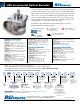
The H25 is the flagship of the BEI Sensors product line. It was designed from the ground
up for the industrial marketplace. The H25 offers features such as EMI shielding, 40 lb.
ABEC 7 bearings, matched thermal coefficients on critical components, and custom high-
efficiency optics. The encoder meets NEMA 4 and 13 requirements when ordered with
the shaft seal. Typical applications include machine control, process control, the wood
processing industry, oil well logging, industrial weighing, agricultural machinery, textile
equipment, web process control, robotics, and food processing.
Mechanical Specifications
Shaft Diameter: 3/8” (1/2”as special feature)
Flat On Shaft: 3/8” Shaft: 0.80 long X 0.03” deep;
1/2” Shaft: 0.80 long X 0.04” deep (1/2’’ shaft w/flat must be
ordered as special feature)
Shaft Loading: 3/8” shaft: Up to 40 pounds axial and 35
pounds radial; 1/2” shaft: Up to 90 pounds axial and 80 pounds
radial
Shaft Runout: 0.0005 T.I.R. at midpoint regardless of
shaft diameter
Starting Torque at 25°C: Without shaft seal 1.0 in-oz (max);
With shaft seal 2.5 in-oz (max); 1/2” shaft with shaft seal:
3.5 in-oz (max)
Bearings: Class ABEC 7 standard, ABEC 5 for 1/2” shaft
Shaft Material: 416 stainless steel
Bearing Housing: Die cast aluminum with protective finish;
stainless steel (special feature)
Cover: Die cast aluminum; stainless steel (special feature)
Bearing Life: 2 X 10
8
revs (1300 hrs at 2500 RPM)
at rated load 1 X 10
10
revs (67,000 hrs at 2500 RPM) at
10% of rated load
Maximum RPM: 12,000 RPM nominal, 8000 RPM with
1/2” shaft (see Frequency Response, below) 30,000 RPM
available on units with 3/8” shaft— consult with factory
Moment of Inertia: 4.1 X 10
-4
oz-in-sec
2
; 5.2 X 10
-4
oz-in-sec
2
with 1/2” shaft
Weight: 13 oz typical, 14.5 oz typical with 1/2” shaft
Electrical Specifications
Code: Incremental
Output Format: 2 channels in quadrature, 1/2 cycle index
gated with negative B channel
Cycles Per Shaft Turn: 1 to 72,000 (see table 2) For resolu-
tions above 3,600 see BEI for interpolation options
Supply Voltage: 5 to 28 VDC available
Current Requirements: 100 mA typical +output load,
250 mA (max)
Voltage/Output: (see note 5)
15V/V: Line Driver, 5–15 VDC in, V
out
= V
in
28V/V: Line Driver, 5–28 VDC in, V
out
= V
in
28V/5: Line Driver, 5–28 VDC in, V
out
= 5 VDC
28V/OC: Open Collector, 5–28 VDC in, OC
out
Protection Level: Reverse, overvoltage and output short circuit
(see note 5)
Frequency Response: 100 kHz, up to 1MHz with interpolation
option (see note 7)
Output Terminations: (See table 1, back)
Note: Consult factory for other electrical options
Environmental Specifications
Enclosure Rating: NEMA 4 & 13 (IP 66) when ordered with
shaft seal (on units with an MS connector) or a cable gland
(on units with cable termination).
Temperature: Operating, 0º to 70º C; extended temperature
testing up to 105°C available; Storage, -25º to 90º C unless
extended temperature option called out.
Shock: 50 g’s for 11 msec duration
Vibration: 5 to 2000 Hz @ 20 g’s
Humidity: 98% RH without condensation
NOTES & TABLES: All notes and tables referred to in the text
can be found on the back of this page.
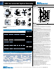
H25 Incremental Ordering Options for assistance call 800-350-2727
Use this diagram, working from left to right to construct your model number (example: H25D-SS-2000-ABZC-28V/V-SM18).
All notes and tables referred to can be found on pages the back of this page.
EXPRESS ENCODERS: Items highlighted with are standard Express Encoders and ship in one to three days.
T2 and T5 options are available as standard H25 Express Encoders.
Special Models of the H25 Incremental Encoder are available with one or more of the
following certifications. Consult factory for details.
SPECIAL
FEATURES:
S = Special
features specified
on purchase order
(consult factory)
See note 6
TYPE:
H = Heavy Duty
25 = 2.500” Dia.
CYCLES PER TURN:
(Enter Cycles)
See Table 2
COMPLEMENTS
C = Complementary
Outputs
Blank = None
See note 4
OUTPUT
TERMINATION:
M12 = MS3112E12-10P
M16 = MS3102R16S-1P
M18 =MS3102R18-1P
C = Pigtail Cable
CS = Cable with seal
Cable length specified in inches
(i.e. C18 = Pigtail 18” long)
See table 1 & note 9
VOLTAGE/OUTPUT:
15V/V = 5–15 V
in/out
28V/V = 5–28V
in/out
28V/5 = 5–28V
in
/5V
out
28V/OC = 5–28V
in
/OC
out
See note 5
OUTPUT
TERMINATION
LOCATION:
E = End
S = Side
HOUSING CONFIG.
LETTER:
D=Square Flange
E=2.50 Dia. Servo Mount
G=2.62 Dia. Servo Mount
See dimensions
OPTIONAL
FACE MOUNTS
F1(E housing only),F2, F3,
or F4
Blank = None
See note 1
SHAFT SEAL
CONFIGURATION:
SS = Shaft Seal
(Not avail. on H25G)
Blank = Shielded Bearing
See note 2
X =
Express
Encoder
NO. OF CHANNELS:
A = Single Channel
AB = Dual Quad. Ch.
ABZ = Dual with Index
AZ = Single with Index
See note 3
H25
HAZARDOUS
AREA RATINGS:
Blank = None
EX = Intrinsically Safe
NI = Non-Incendive
Contact factory for
voltage options
C
Canadian Standards
Class I, Zone 0, Group IIC
U.S. Standards Class I,
Group A,B,C & D;
Class II Group E, F & G
CENELEC
II 1 G Ex ia IIB/IIC T4
II 3 G Ex nA IIB T4 Gc
EN 55011 and EN 61000-6-2
Class I, Div 2, Group A,B,C & D;
Class II, Div 2, Group F & G
UL 12.0035X
UL 12.0082X