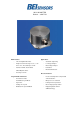
INCLI NO METER RS232 – SW ITCH Main Features - - Applications Two axis digital inclinometer - Structural engineering Angle measurement range of +/-5°, +/-15° - Leveling techniques and +/-30°–, Resolution up to 0.
INCLI NO METER RS232 – SW ITCH 1 Technical Data 1.1 Electrical Data Model INC 5 INC 15 INC 30 Measuring range +/- 5° +/- 15° +/- 30° Resolution digital 0.001° 0.001° 0.01° Resolution switch 0,1° 0,1° 0,1° Accuracy switch +/-0,1° +/-0,1° +/-0,1° +/-0,01° +/-0,01° +/-0,02° +0.001°/K +0.002°/K +0.003°/K +/-15° +/-40° +/-60° Accuracy digital 1) Temperture Gradient 2) Inclination angle in x and y 1) Damping period 5° > 0° Typical 1 s 10 %, 2 s 1 %, 3 s 0.
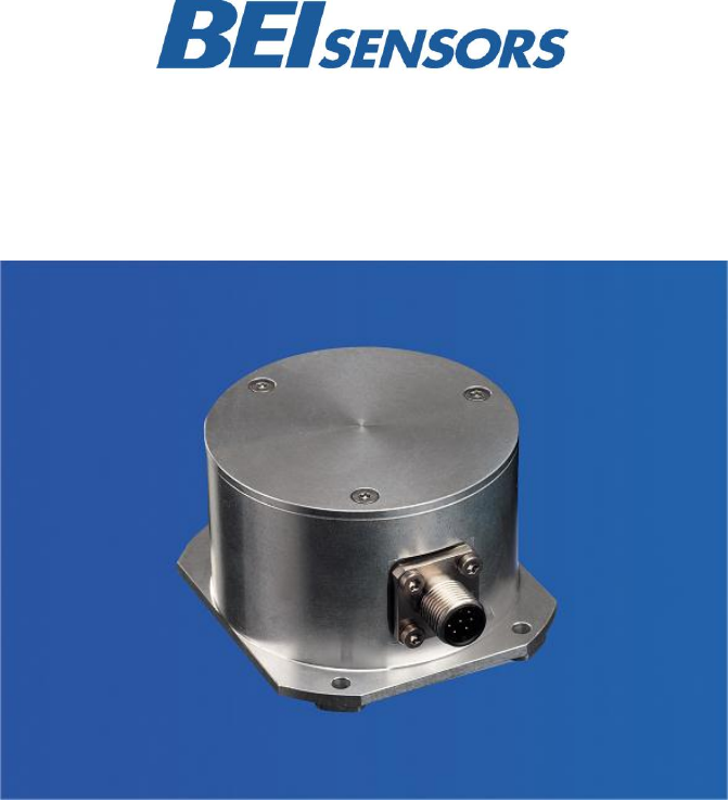
INCLI NO METER RS232 – SW ITCH 1.2 Mechanical Data Housing Aluminum Lifetime > 10 h Shock A=30 g ; t= 11 ms, halfsine ; EN 60068-2-27 Vibration 10 to 150 Hz, 2,5 mm amplitude, 5 g const. Acceleration, 5 1 Octave /Minute ; EN 60068-2-6 Weight (standard version) 350 g 1.
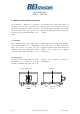
INCLI NO METER RS232 – SW ITCH 2 Installation 2.1 Electrical Connection The inclinometer is connected via 8 pin round connector or a cable 2.2 Connector Assignment Pin Description P8F-Cable CRW-Cable 1 +UB Supply voltage white white 2 RxD brown brown 3 TxD green green 4 Ground (Supply) yellow yellow 5 X-Output grey grey 6 S-Ground pink pink 7 Y-Output blue red 8 – red – Front view of housing Connector inclinometer Output signal (X, Y) switch, 0.
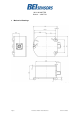
INCLI NO METER RS232 – SW ITCH 3 Mechanical Drawings Dimension Housing (mm) Page 5 Inclinometer RS232 – Switch Datasheet Version: 20130503
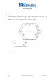
INCLI NO METER RS232 – SW ITCH 4 Reference Level The Inclinometer has a mounting reference angle placed exactly parallel to the object to be (black line) for an optimal mounting, which is measured, to prevent or minimize any mechanical parallel to the x-axis. This reference angle must be offset/cross sensitivity. Reference edge, base plate side Reference angle of the inclinometer, top view.
INCLI NO METER RS232 – SW ITCH 5 Mounting and Installation Instruction The inclinometer is designed for a horizontal The mounting surface must be plane and free of mounting, i.e. the base plate of the inclinometer dust and grease. We recommend cheese head with the three mounting holes needs to be placed screws with metrical thread M4for the mounting. on the horizontal plane of the object to be Maximum fastening torque for the mounting screws measured. It can be mounted with M4 screw or is 10 Nm.
INCLI NO METER RS232 – SW ITCH 6 Models/Ordering Description Description Type Key Absolute Inclinometer INC- ___ Measuring range -2-S _ 1-H0- ___ 005 015 030 Number of axis RS232 without Interface O Volltage interface V Current interface C PWM P Switch S Version Mounting Dynamic Horizontal Connection plug, 8 pins P8M 1 m cable exit CRW Optionen Page 8 2 m Pas – Inclinometer RS232 – Switch Datasheet Version: 20130503
INCLI NO METER RS232 – SW ITCH 7 Serial Interface RS 232 Communication with the sensor is done through a permanently modified. If the continuous mode was standardized RS-232 interface. Data transmission permanently changed to the polling mode, the is effected in duplex mode. The baud rate is fixed sensor will send after Power On a start information by 9600 baud. After Power On the sensor is with actual parameters.
INCLI NO METER RS232 – SW ITCH 8 Programming Instructions 8.1 Basic Settings After Power On, the sensor is in the user level. In rate and angle offset. If query mode instead of free factory setting (=Free running mode) every 100ms running mode is selected, the sensor will send the current angle values are continuously supplied start information with the current settings after with a baud rate of 9600 bd. In the Setup-level Power On.
INCLI NO METER RS232 – SW ITCH 9 Commands in User Level Instruction To the Response sensor Description „f“ the continuous sending of sensor activate temporary polling „f“ mode angle values are stopped, instructions can send to the sensor activate temporary continuous „F“ mode „X=vxx.xxx“, CR, LF, X angle in ° „Y=vxx.xxx“, CR, LF, Y angle in ° „X= with „±” = „+“ or „-“, ... one string contains x and y value „R“ read angle values „X=vxx.xxx“, CR, LF, X angle in ° „Y=vxx.
INCLI NO METER RS232 – SW ITCH 10 Setup Level The Setup level is active until ”Power On” or Reset. the EEPROM and permanent available also after All settings taken in the setup level are stored in Power down.
INCLI NO METER RS232 – SW ITCH 10) Exponential Filter „M2“, „tt“ „M2tt“ Filter: Exponential Filter is activated Set switch angle for one axis 2) 3) 7) 8) “Sx“ “Sx“ or “Sy” Echo, switch angle or „E“ or “Sy“ for Error, if the angle is outside admissible range Set hysteresis for “Sh“ “Sh“ Echo, hysteresis or „E“ switching point in both for Error, if the angle is axis 2) 3) 7) 9) show active level Reset outside adm
INCLI NO METER RS232 – SW ITCH Strings per second, 1 string contains x and y-value “0“ reserved “1“ 25 Strings/s “2“ 10 Strings/s, Default value “3“ 5 Strings/s “4“ 2 Strings/s “5“ 1 Strings/s “6“ 0,2 Strings/s “7“ 0,1 Strings/s “8“, “9” not defined 1) 2) 1) 2) only allowed with baud rate of at least 9600 Bd only allowed with baud rate of at least 4800 Bd Baud rate “0“ 2400 Baud “1“ 4800 Baud “2
INCLI NO METER RS232 – SW ITCH Example for Setting the Output Rate Instruction To the sensor Response sensor Description „X=±xx.xxx“, CR, LF, continuous sending of ”Y=±xx.xxx“, CR, LF, angles ”X= activate temporary ”f” ...