
Manual


Page 12 Inclinometer RS232 – Switch Datasheet Version: 20130503
INCLINOMETER
RS232 – SWITCH
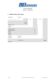
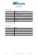
10 Setup Level
The Setup level is active until ”Power On” or Reset.
All settings taken in the setup level are stored in
the EEPROM and permanent available also after
Power down.
Instruction
To the sensor
Response sensor
Description
activate permanent
polling mode
1)
“f“
“f“
the continuous sending of
angle values are
permanent stopped,
instructions can send to
the sensor
activate permanent
continuous mode
1)
“F“
„X=±xx.xxx“, CR, LF,
”Y=±xx.xxx“, CR, LF,
”X= . . .
continuous sending of
X angle in °
Y angle in °
with „±” = „+“ or „-“
set rate of data
transmission for
continuous mode
2) 3) 4)
“O“
<Code transmission
rate>
“O”
<Code transmission
rate>
Echo,
Code transmission rate
or „E“ for Error, if the
code is outside defined
values
read angle values at
one-time
2)
“R“
same as at user level
read version
2)
“V“
“AGSxxx-2-Sx“, CR,
LF
”SN:xxxx-xxx“, CR,
LF
”HV:xx.x“ , CR, LF
”SV:xx.x“ , CR, LF
type of Sensor
serial number
HW Version internal
sensor
SW Version
offset adjust of the
specified axis
2) 3)
“n“
”x“ or ”y“
“n“
”OffsetX=±xx.xxx“ or
”OffsetY=±xx.xxx“
the actual angle of
specified axis is set to
zero, ±xx.xxx is the
internal offset in
degree
reset offset adjust
2) 3)
“N“
“N“
the offset adjust was
reset to the original value
Set Baud rate
2) 3) 6)
“B“
<Code Baud rate>
“B“
<Code Baud rate>
Echo, Code Baud rate or
„E“ for Error, if the code
is outside defined values
Filter deactivated
„M0“
„M0“
all filters are deactivated
Moving Average
Filter
10)
„M1“, “mm“
„M1mm“
Filter: Moving Average
Filter is activated