
Manual
Page 4 Inclinometer RS232 – Switch Datasheet Version: 20130503
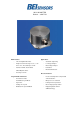
INCLINOMETER
RS232 – SWITCH
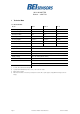
2 Installation
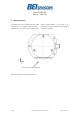
2.1 Electrical Connection
The inclinometer is connected via 8 pin round connector or a cable
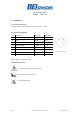
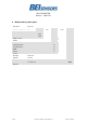
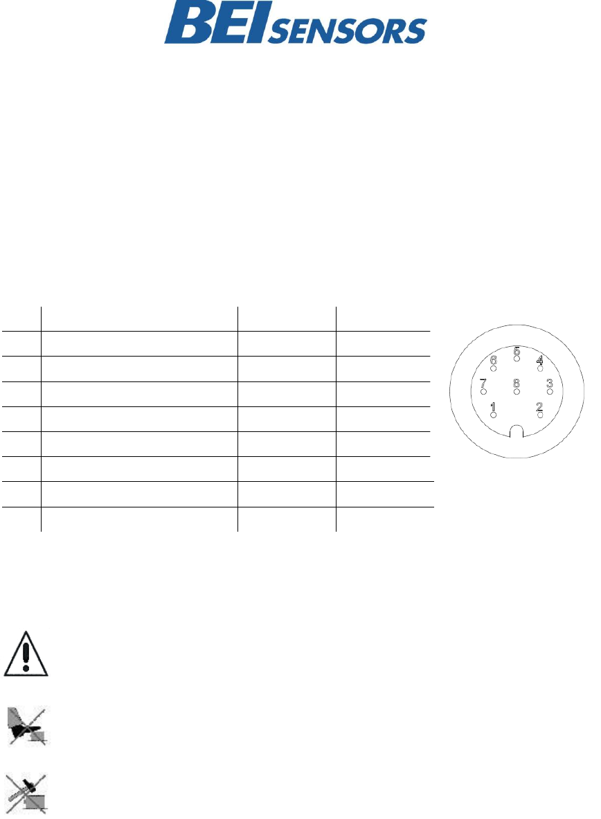
2.2 Connector Assignment
Pin
Description
P8F-Cable
CRW-Cable
1
+UB Supply voltage
white
white
2
RxD
brown
brown
3
TxD
green
green
4
Ground (Supply)
yellow
yellow
5
X-Output
grey
grey
6
S-Ground
pink
pink
7
Y-Output
blue
red
8
–
red
–
Output signal (X, Y) switch, 0.1° step
Installation Instructions
Do not connect the inclinometer under power!
Do not stand on the inclinometer!
Avoid mechanical load!
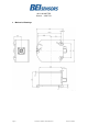
Front view of housing
Connector inclinometer