
Manual


APPLICATIONNOTEAN‐BEI‐H2‐038 Date:15/02/12
AN‐BEI‐H2‐038ModbusRTUControlandRegisterMapping
4
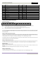
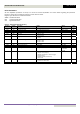
61 Userregister11 03,06 Read/Write
62 Userregister12 03,06 Read/Write
63 Userregister13 03,06 Read/Write
64 Userregister14 03,06 Read/Write
65 Userregister15 03,06 Read/Write
66 Analogoutput1user 03,06 Read/Write
67 Analogoutput2user 03,06 Read/Write
68 Reserved 03,06 Read/Write
69 Reserved 03,06 Read/Write
70 Relayoutput1user 03,06 Read/Write
71 Relayoutput2user 03,06 Read/Write
72 Relayoutput3user 03,06 Read/Write
73 Relayoutput4user 03,06 Read/Write
74 Relayoutput5user 03,06 Read/Write
75 Userdisplayscaling 03,06 Read/Write
76 Userdisplaydecimal 03,06 Read/Write
77 Userspeedreference 03,06 Read/Write
78 Usertorquereference 03,06 Read/Write
79 Userramp 03,06 Read/Write
80 Scopeindex1,2 03,06 Read/Write
ControlandStatusRegisterDescriptions:
Readandwriteregisters
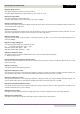
Register1:DriveControlCommandWord
15 14 13 12 11 10 9 8 7 6 5 4 3 2 1 0
Highbyte Lowbyte
Bit0: Run/Stopcommand:Setto1toenable(run)thedrive.Setto0todisable(stop)thedrive.
Bit1: Faststoprequest.Whensetto1thedrivewilldeceleratetostopusingthe2
nd
decelerationramp(P2‐25).
Bit2: ResetFaultRequest.Setto1inordertoresetthedrivefollowingatrip/fault.
(Note:Thisbitmustberesettozerooncethefaultisclearedtopreventun‐expectedreset)
Bit3: Coaststoprequest.Setto1
toissueacoaststopcommand.
Fornormaloperation,Bit3hasthehighestpriority,bit0hasthelowestpriority(bit3>bit1>bit0).Forexampleifthecontrol
wordissetto0x0009bythenetworkmaster,thedrivewilldoacoaststopratherthanrun.For
normalStart/Stopoperation,
bit0shouldbeused.
Register2:ModbusSpeedReferenceSetpoint
Thisregisterisusedtosendthespeedreferencevalue.Theinputdataisa16bitsignedintegerincludingonedecimalplace.For
example,avalueof500representsaspeedreferenceof50.0Hz,
123represents12.3Hz.Itisalsopossibletoreversethedriveby
sendinganegativevalueinthisregister.Forexample,‐1(0xFFFF)gives‐0.1Hz.‐234(0xFF16)gives‐23.4Hz.
The input value range is from‐5000 +5000; however the actual drive output frequency will be limited by the minimum and
maximumfrequencies
setinP1‐02andP1‐01respectively.
Register4:ModbusRampControlTime
Thisregisterspecifiesthedriveaccelerationanddecelerationramptimesimultaneously.Thisvaluewilloverridethevaluessetin
parametersP1‐03andP1‐04respectively,providingP5‐08=1.Theinputdatarangeis
from0to60000(0.00sto600.00s)
Readonlyregisters
Register6:Drivestatusanderrorcode
High byte : Shows the last drive error / fault code. (Valid when the drive is tripped,a list of error codes is shown later in this
document)
Lowbyte:Showsthe
driveoperatingstatus(0:drivestopped,1:driverunning,2:drivetipped)
Register7:OutputFrequency
Thisregistershowstheoutputfrequency.
Thedatais16bitintegerwithonedecimalplace.E.g.value123gives12.3Hz.Value‐234(0xFF16)gives‐23.4Hz.