EXTER™ K20m Installation manual MAEN852A, 2008-05 English
Foreword Installation manual for the EXTER series operator panels Foreword The EXTER operator panel is developed to satisfy the demands of human-machine communication. Built-in functions such as displaying and controlling text, dynamic indication, time channels, alarm and recipe handling are included. The operator panel work, for the most part, in an object-oriented way, making it easy to understand and use.
Table of Contents Table of Contents 1 Safety Precautions................................................................................. 1.1 UL and cUL Installation ................................................................... 1.2 General ............................................................................................. 1.3 During Installation............................................................................ 1.4 During Use ........................................................
Table of Contents Beijer Electronics, MAEN852A
Safety Precautions 1 Safety Precautions Both the installer and the owner and/or operator of the operator panel must read and understand this installation manual. 1.1 UL and cUL Installation – This equipment is suitable for use in Class I, Division 2, Groups A, B, C and D OR non-hazardous locations only. [Combinations of equipment in your system are subject to investigation by the local Authority Having Jurisdiction at the time of installation.
Safety Precautions 1.2 General – Read the safety precautions carefully. – Check the delivery for transportation damage. If damage is found, notify the supplier as soon as possible. – Do not use the operator panel in an environment with high explosive hazards. – The supplier is not responsible for modified, altered or reconstructed equipment. – Use only parts and accessories manufactured according to specifications of the supplier.
Safety Precautions 1.4 During Use – Keep the operator panel clean. – Emergency stop and other safety functions may not be controlled from the operator panel. – Do not use too much force or sharp objects when touching the keys, touch screen etc. 1.5 Service and Maintenance – Only qualified personnel should carry out repairs. – The agreed warranty applies. – Before carrying out any cleaning or maintenance operations, disconnect the equipment from the electrical supply.
Safety Precautions 8 Beijer Electronics, MAEN852A
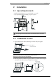
Installation 2 Installation 2.1 Space Requirements – Installation plate thickness: 1.5 - 7.5 mm (0.06 - 0.3 - inch) – Space requirements when installing the operator panel: 100 mm (4.0 inch) 155 mm (6.10 inch) 100 mm (4.0 inch) 50 mm (2.0 inch) 50 mm (2.0 inch) 100 mm (4.0 inch) 155 mm (6.10 inch) 46.4 mm (1.83 inch) Caution The openings on the enclosure are for air convection. Do not cover these openings. 2.2 Installation Process 1. Unpack and check the delivery.
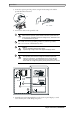
Installation 3. Secure the operator panel in position, using all the fastening holes and the provided brackets and screws: x6 0.5 - 1.0 Nm 4. Connect the cables in the specified order. A Caution Ensure that the operator panel and the controller system have the same electrical grounding (reference voltage level), otherwise errors in communication may occur. B Use an M5 screw and a grounding conductor (as short as possible) with a cross-section of minimum 2.5 mm2.
Installation 2.2.1 Mode Switches All mode switches must be in OFF position during operator panel use. The mode switches should not be touched unless by qualified personell. ON DIP 1 2 3 4 2.2.2 Connections to the Controller For information about the cables to be used when connecting the operator panel to the controller, please refer to the help file for the driver in question. 2.2.
Installation 12 Beijer Electronics, MAEN852A
Technical Data 3 Technical Data Parameter EXTER K20m Front panel, W x H x D 155 x 155 x 6 mm Mounting depth 46.4 mm Front panel seal IP 66 Rear panel seal IP 20 Keyboard material Membrane switch keyboard with metal domes. Overlay film of Autotex F207 * with print on reverse side. 1 million operations. Reverse side material Powder-coated aluminum Weight 0.55 kg Serial port RS422/ RS485 25-pin D-sub contact, chassis-mounted female with standard locking screws 4-40 UNC.
Technical Data 14 Beijer Electronics, MAEN852A
Chemical Resistance 4 Chemical Resistance 4.1 Metal Casing The frame and casing material is powder-coated aluminum.
Chemical Resistance Acetic acid (<50%) Gumption1 SBP 60/951 Ariel powder in solution1 Hydrochloric acid (<36%) Sulfuric acid (<10%) Linseed oil Tomato ketchup 1 Bleach Castor oil Methanol Trichloroacetic acid (<50%) Caustic soda (<40%) Nitric acid (<10%) White Spirit Cutting oil Paraffin oil Windex1 Cyclohexanol Persil powder in solution1 Wisk Diacetone alcohol Petroleum spirit1 - 1 1 Extremely faint glossing of the texture was noted.
Operator Panel Drawings 5 Operator Panel Drawings 5.1 Communication Ports RS-232 RS-422 RS-485 RS-422/485 Drawing No.
Operator Panel Drawings 5.2 EXTER K20m Outline Drawing No.
Operator Panel Drawings 5.3 EXTER K20m Text Strip (unit: mm) 9.0 4.5 11.25 19.0 20.5 20.5 138.0 20.5 19.0 Text max 18.5x7.5 Text max 15.5x7.5 R1 (4x) Drawing No.
Operator Panel Drawings 20 Beijer Electronics, MAEN852A
Additional Installation Tips 6 Additional Installation Tips When experiencing communication problems in for example noisy environments or when operating close to temperature limits, the following recommendations are to be noticed. 6.1 Grounding the Operator Panel Door Mounting plate in the cabinet Operator panel 3 2 Power supply 1 Ferrite core 24 V DC 5 6 4 1. The operator panel’s mounting clamps do not provide a secure grounding connection between the panel and the device cabinet. 2.
Additional Installation Tips 6.2 Ethernet Connection in the Panel Industrial Ethernet RJ45 RJ45 1 RJ45 RJ45 Operator panel RJ45 3 2 Operator panel RJ45 4 Shielded 1-1 2-2 3-3 Short and unshielded Operator panel RJ45 8-8 5 Operator panel RJ45 0.1 uF 250 V 5351 1. In some industrial units for Ethernet, the RJ45 contact’s shield is connected to the chassis via a capacitor. 2. The operator panel’s Ethernet shield is directly connected to the chassis.
Additional Installation Tips 6.3 To Achieve Better EMC Protection – – – – – – – – Initially, use the original cabling from Beijer Electronics primarily. Use shielded cables for RS232 communication. Use twisted pair and shielded cabling for RS422 and RS485. Use the cabling intended for the bus type; Ethernet, Profibus, CC-Link, CAN, Device Net etc. Install and connect according to applicable specifications for the relevant bus standard.
Additional Installation Tips 6.4 Ambient Temperature The maximum ambient temperature for the operator panel is provided in the specifications. The ambient temperature refers to the temperature in the device cabinet which cools the panel’s electronics.
Additional Installation Tips 6.5 Safety Most of the operator panels are fed with 24 V DC. Power supply 230 V AC to 24 V DC Operator panel +24 V 1 0V 4 Power supply 230 V AC to 24 V DC Operator panel +24 V 2 0V 4 Distance? Power supply 230 V AC to 24 V DC Operator panel +24 V 3 0V 4 COM1 Small controller with expansion unit Ch0 Ch1 230 V AC COM100 Ch100 Ch101 5355 1. If you use a power supply that meets safety standards and only feeds the operator panel, there is no problem. 2.
Additional Installation Tips 6.6 Galvanic Isolation Internal electronic Filter Ethernet DC/DC galvanic isolation DC/AC VCC +24 V DC CFL 0 V (GND) 0V 1.5 m RS422/485 RS232 USB 5356 USB The operator panel has galvanic isolation against the 24 V DC feed but no galvanic isolation between the communication ports for RS232, RS422/485 and USB. Only the Ethernet connection has galvanic isolation.
Additional Installation Tips 6.7 Cable and Bus Termination RS485 – Use shielded and twisted pair cable. The pair capacitance may not exceed 52.5 pF/m and area at least 0.25 mm2 (AWG 24), if you want to use the maximum transfer distance and maximum transfer speed. – 0 V, the reference voltage for communication should be included in the cabling. With two-way communication use two pairs; one pair for communication and one pair for 0 V. – The shield must be grounded at one end.
HEAD OFFICE SUBSIDIARIES SWEDEN GERMANY USA Beijer Electronics Products AB Box 426 SE-201 24 Malmö, Sweden Tel: +46 40 35 86 00 Fax: +46 40 93 23 01 info@beijerelectronics.com Elektronik-Systeme Lauer GmbH & Co. KG Kelterstraße 59 72669 Unterensingen, GERMANY Tel: +49 7022 9660 0 Fax: +49 7022 9660 103 info@systeme-lauer.de Beijer Electronics Inc. 939 N. Plum Grove Road, Suite F Schaumburg, IL 601 73, USA Tel: +1 847 619 6068 Fax: +1 847 619 6674 info.usa@beijerelectronics.