
Manual


Additional Installation Tips
Beijer Electronics, MAEN852A 21
6 Additional Installation Tips
When experiencing communication problems in for example noisy environments or
when operating close to temperature limits, the following recommendations are to be
noticed.
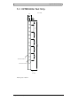
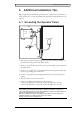
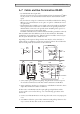
6.1 Grounding the Operator Panel
1. The operator panel’s mounting clamps do not provide a secure grounding con-
nection between the panel and the device cabinet.
2. Connect a 2.5 mm
2
wire between the operator panel’s quick-connect plinth and
the panel chassis.
3. Connect a 6 or 4 mm
2
wire or grounding braid between the panel’s chassis and
the closest grounding point on the door.
4. Connect a strong but short grounding braid between the door and the device
cabinet.
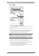
5. Twist the cables onto the 24 V DC feed.
6. A ferrite core suppresses disturbances to the 24 V feed.
2 turns around the ferrite core provide 4 times the suppression of 1 turn.
3 turns around the ferrite core provide 9 times the suppression of 1 turn.
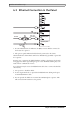
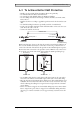
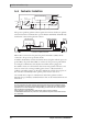
Remember:
The grounding wires should be short and the conductor should have a large area.
A long, thin grounding wire has a very high impedance (resistance) at high frequencies
and will not guide disturbances to the ground.
Multi-wire conductors are better than single wire conductors with the same area.
A braided conductor wire with the same area is even better.
The best is a short, thick grounding braid.
1
2
3
4
5
6
Door
Operator panel
Ferrite core
Mounting plate in the cabinet
Power supply
24 V DC