iX Panel T100 Service & Maintenance Manual MAEN007, 2010-05 English
Foreword Service & Maintenance manual for iX Panel T100 Foreword This manual contains detailed information about iX Panel T100, including descriptions of various actions that can be carried out in order to maintain or update the operator panel hardware and software. The manual contains descriptions of basic maintenance and replacement of common parts in iX Panel T100. The manual assumes that the most recent versions of the system program (firmware) and iX Developer are used.
Contents Contents 1 Safety Precautions ....................................................... 1.1 General ........................................................... 1.2 During Installation .............................................. 1.3 During Use ....................................................... 1.4 Service and Maintenance ........................................ 1.5 Dismantling and Scrapping ..................................... 2 Introduction ..................................................
Contents 9.3.3 9.3.4 9.3.5 Erase Project . . . . . . . . . . . . . . . . . . . . . . . . . . . . . . . . . . . . . . . . . . . . . . . . . . . . . 30 Format Memory Card . . . . . . . . . . . . . . . . . . . . . . . . . . . . . . . . . . . . . . . . . . . 30 Touch Calibrate . . . . . . . . . . . . . . . . . . . . . . . . . . . . . . . . . . . . . . . . . . . . . . . . . 30 10 Hardware Self Test ...................................................... 11 Additional Installation Tips .........................
Safety Precautions 1 Safety Precautions Both the installer and the owner and/or operator of the operator panel must read and understand this installation manual. 1.1 • • • • • • • • • • • • General Read the safety precautions carefully. Check the delivery for transportation damage. If damage is found, notify the supplier as soon as possible. Do not use the operator panel in an environment with high explosive hazards. The supplier is not responsible for modified, altered or reconstructed equipment.
Safety Precautions 1.3 • • • Keep the operator panel clean. Emergency stop and other safety functions may not be controlled from the operator panel. Do not use too much force or sharp objects when touching the keys, touch screen etc. 1.4 • • • • • • Service and Maintenance Only qualified personnel should carry out repairs. The agreed warranty applies. Before carrying out any cleaning or maintenance operations, disconnect the equipment from the electrical supply.
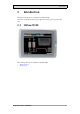
Introduction 2 Introduction This manual describes how to maintain the iX Panel T100. The functions available in iX Developer depend on which operator panel model is used. 2.
Introduction 2.2 Maintenance Carefully read the instructions before beginning maintenance on the operator panel. • Only qualified personnel should carry out maintenance. • The agreed warranty and license agreements apply. • Any damage to the operator panel caused by personnel invalidates the warranty. • Before carrying out any cleaning or maintenance operations, disconnect the operator panel from the power supply. • Clean the display and surrounding front cover with a soft cloth and mild detergent.
Introduction 2.5 Contact and Support If you want to report a fault or have a question about the operator panels, please contact your local supplier or fill out the form on the web site. 1. Enter the web site www.beijerelectronics.com and select Support. 2. Select Contact in the menu. Make sure to provide information about type number, serial number, environment and an installation description.
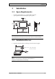
Installation 3 Installation 3.1 Space Requirements • • Installation plate thickness: 1.5 - 9.0 mm (0.06 - 0.35 inch) Space requirements when installing the operator panel: 100 mm (4.0 inch) 228 mm (8.98 inch) 50 mm (2.0 inch) 100 mm (4.0 inch) 50 mm (2.0 inch) 100 mm (4.0 inch) 58 mm (2.28 inch) 302 mm (11.89 inch) Caution: The openings on the enclosure are for air convection. Do not cover these openings. 3.2 Installation Process 1. Unpack and check the delivery.
Installation 2. Place the panel cut out where the operator panel is to be situated, draw along the outer sides of the holes and cut according to the markings. 3. Secure the operator panel in position, using all the fastening holes and the provided brackets and screws: x 13 0.5 - 1.
Installation 4. Connect the cables in the specified order, according to the drawing and steps below. Caution: • Ensure that the operator panel and the controller system have the same electrical grounding (reference voltage level), otherwise errors in communication may occur. • The operator panel must be brought to ambient temperature before it is started up. If condensation forms, ensure that the operator panel is dry before connecting it to the power outlet.
Installation 3.2.1 Connections to the Controller For information about the cables to be used when connecting the operator panel to the controller, please refer to the help file for the driver in question. 3.2.2 Other Connections and Peripherals Cables, peripheral equipment and accessories must be suitable for the application and its environment. For further details or recommendations, please refer to the supplier.
Technical Data 4 Technical Data Parameter iX Panel T100 Front panel, W x H x D 302 x 228 x 6 mm Mounting depth 58 mm (158 mm including clearance) Front panel seal IP 66 Rear panel seal IP 20 Keyboard material/Front panel Touch screen: Polyester on glass, 1 million finger touch operations. Overlay: Autotex F157 or F207*. Reverse side material Powder-coated aluminum Weight 2.
Chemical Resistance 5 Chemical Resistance 5.1 Metal Casing The frame and casing material is powder-coated aluminum.
Chemical Resistance 5.2 Touch Screen and Overlay 5.2.1 Autotex F157/207 Autotex F157 or F207 covers the overlay surrounding the touch screen.
Chemical Resistance 5.2.2 Touch Screen Surface The touch screen surface on the panel withstands exposure to the following solvents without visible change: Solvents Time Acetone 10 minutes Isopropanol 10 minutes Toluene 5 hours 5.2.3 Autoflex EB It is recommended to use the Autoflex EB touch display protection film, that can be ordered from Beijer Electronics. Solvent Resistance Autoflex EB withstands exposure to the same chemicals as Autotex F157 or F207 according to section Autotex F157/207.
Hardware Tests 6 Hardware Tests Before the operator panels are approved for market introduction, they are tested by independent authorities. The iX Panels are examined by several authorities before being approved for market introduction. All operator panels are designed to fulfill standards such as CE. The quality policy and environmental policy place demands on all suppliers and subcontractors. The manufacturer performs extensive hardware testing before an operator panel is approved.
Additional Hardware 7 Additional Hardware 7.1 Memory Card An internal Compact Flash memory card can be used in iX Panel T100 for expansion of the project memory. Note: When using an internal Compact Flash memory card, no external Compact Flash memory card can be used. An external USB Flash drive can be used for the same functions as an external Compact Flash card. Compact Flash cards of type I and II are supported.
Additional Hardware 5. Re-attach the back cover to the operator panel. 6. Turn on the power to the operator panel. When the operator panel starts up, you will be asked if you like to move the files to the internal card; select YES to this question. 7.1.2 Settings in iX Developer The size of the internal memory card must be entered in iX Developer. 1. Click on Settings on the Project group of the Project ribbon tab. 2. Select the Display/Panel properties.
Hardware Replacement 8 Hardware Replacement This section contains instructions on how to replace operator panel hardware. Only components included in the latest bill of material and spare parts list are allowed. See Available Spare Parts for iX Panel T100. 8.1 Mode Switches The iX Panel T100 has four mode switches (DIP switches) located on the rear side of the operator panel.
Hardware Replacement MODE Description 1100 Not used (run mode). 1110 Self-test. xxx1 Hard reset (forces the system to reset). To change mode switches, follow the steps below: 1. Disconnect power from the operator panel. 2. Set the mode switches using a ballpoint pen. 3. Reconnect power to the operator panel. 8.2 Cables Most of the operator panels use the same type of flex cable connectors.
Hardware Replacement 8.3 Replacing the Rear Cover The following is needed: • A new rear cover, see Available Spare Parts for iX Panel T100 • A torx T10 screwdriver Note: Make sure to use adequate ESD protection. Follow the steps below to replace the rear cover: 1. Power off the operator panel. 2. Remove the rear cover of the operator panel by loosening the 4 torx screws. 4 x torx screws 3. Re-assemble with the new rear cover in reverse order.
Hardware Replacement 8.4 Replacing the Display/Display Cable The following is needed: • A new display/display cable, see Available Spare Parts for iX Panel T100 • A torx T10 screwdriver Note: Make sure to use adequate ESD protection. Follow the steps below to replace the display/display cable: 1. Power off the operator panel. 2. Follow the instructions under Replacing the Rear Cover to remove the rear cover. 3.
Hardware Replacement 5. Remove the mounting plate (9 torx screws). Gently lift the mounting plate with the display and power card. 9 x torx screws 6. Flip the mounting plate and unscrew the 4 torx screws. 4 x torx screws 7. Re-assemble the panel in reverse order. 8.4.1 Self-test of the Display To perform a self-test of the display, follow the steps below: 1. Start the operator panel in a self-test mode (see table in the Mode Switches section). 2. Go to the display test.
Hardware Replacement 8.5 Replacing the Complete Front The following is needed: • A new front, see Available Spare Parts for iX Panel T100 • A torx T10 screwdriver Note: Make sure to use adequate ESD protection. Follow the steps below to replace the complete front of the iX Panel T100: 1. Power off the operator panel. 2. Follow the steps 1-3 and 5 in the Replacing the Display/Display Cable instructions, but in step 3, only disconnect the flex cables and the LED cable (do not remove the power card). 3.
Hardware Replacement 8.6 Replacing the Backlight Note: All lamps in the display must be replaced at the same time. The following is needed: • A new backlight, see Available Spare Parts for iX Panel T100 • A torx T10 screwdriver Note: Make sure to use adequate ESD protection. Follow the steps below to replace the battery of the iX Panel T100: 1. First, follow the steps 1–5 in section Replacing the Rear Cover. 2.
Hardware Replacement 8.
Service Menu 9 Service Menu The service menu for the operator panel can be accessed before a project is downloaded, or by setting the mode switches in mode 1000. The location of the mode switches is described in the Mode Switches section. 9.1 Service Menu in an Empty Panel When no project is loaded in the panel memory, the panel will boot, displaying the Welcome screen. Press anywhere on the panel display to enter the service menu. 9.
Service Menu 9.3.3 Erase Project The erase function will detect if the project is located in the panel memory or on a memory card. Pressing Erase Project will completely remove the project and all its components from the panel memory/the memory card. 9.3.4 Format Memory Card The format memory card function will detect if external and internal memory cards. Select which card to format and, in some cases, formatting alternatives. 9.3.
Hardware Self Test 10 Hardware Self Test The self-test program can be used to test aspects of operator panel functionality and the communication ports. To run the test you will need: • Test plugs; see Test plug drawing. • 24 V DC, min. 3 A. Follow the steps below to run the self-test program on the operator panel: 1. Power off the operator panel. 2. Go to the self-test. Set the mode switches to the self-test positions, see the table in the Mode Switches section. 3.
Additional Installation Tips 11 Additional Installation Tips When experiencing communication problems in for example noisy environments or when operating close to temperature limits, the following recommendations are to be noticed. 11.
Additional Installation Tips 11.2 Ethernet Connection in the Panel Industrial Ethernet RJ45 RJ45 1 RJ45 RJ45 Operator panel RJ45 3 2 Operator panel RJ45 4 Shielded 1-1 2-2 3-3 Short and unshielded Operator panel RJ45 8-8 5 Operator panel RJ45 0.1 uF 250 V 5351 In some industrial units for Ethernet, the RJ45 contact’s shield is connected to the chassis via a capacitor, see 1 in drawing above. The operator panel’s Ethernet shield is directly connected to the chassis, see 2 in drawing above. 1.
Additional Installation Tips 11.3 To Achieve Better EMC Protection • • • • • • • • Initially, use the original cabling from Beijer Electronics primarily. Use shielded cables for RS232 communication. Use twisted pair and shielded cabling for RS422 and RS485. Use the cabling intended for the bus type; Ethernet, Profibus, CC-Link, CAN, Device Net etc. Install and connect according to applicable specifications for the relevant bus standard.
Additional Installation Tips 11.4 Ambient Temperature The maximum ambient temperature for the operator panel is provided in the specifications. The ambient temperature refers to the temperature in the device cabinet which cools the panel’s electronics.
Additional Installation Tips 11.5 Safety Most of the operator panels are fed with 24 V DC. Power supply 230 V AC to 24 V DC Operator panel +24 V 1 0V 4 Power supply 230 V AC to 24 V DC Operator panel +24 V 2 0V 4 Distance? Power supply 230 V AC to 24 V DC Operator panel +24 V 3 0V 4 COM1 Small controller with expansion unit Ch0 Ch1 230 V AC COM100 Ch100 Ch101 5355 If you use a power supply that meets safety standards and only feeds the operator panel, there is no problem.
Additional Installation Tips 11.6 Galvanic Isolation Internal electronic Filter Ethernet DC/DC galvanic isolation DC/AC VCC +24 V DC CFL 0 V (GND) 0V 1.5 m RS422/485 RS232 USB 5356 USB The operator panel has galvanic isolation against the 24 V DC feed but no galvanic isolation between the communication ports for RS232, RS422/485 and USB. Only the Ethernet connection has galvanic isolation.
Additional Installation Tips 11.7 Cable and Bus Termination RS485 Use shielded and twisted pair cable. The pair capacitance may not exceed 52.5 pF/m and area at least 0.25 mm2 (AWG 24), if you want to use the maximum transfer distance and maximum transfer speed. 0 V, the reference voltage for communication should be included in the cabling. With two-way communication use two pairs; one pair for communication and one pair for 0 V. The shield must be grounded at one end.
Fault Tracing 12 Fault Tracing This section includes different fault scenarios and steps to follow to trace the fault. The iX Panel T100 is not working properly, and the power LED is off 1. 2. 3. 4. 5. Is the power voltage correct? Does the power supply deliver enough current? Check the fuse. Check the power card. Is the power card correctly mounted? The iX Panel T100 is not communicating with the controller 1. 2. 3. 4. Check the communication cable between the units.
Fault Tracing The iX Panel T100 is working, but one or more keys are not working 1. Check that the flex cables are correctly fitted. 2. Replace the front according to the Replacing the Rear Cover section. The touch screen is malfunctioning or is not responding at all 1. Re-calibrate the touch screen according to the Calibrating the Touch Screen section. 2. Check that the flex cable is correctly fitted. 3. Replace the display of the operator panel according to the Replacing the Display/Display Cable section.
Software 13 Software This chapter describes how to maintain and update the software in the iX Panels. The chapter includes a general description of the operator panel software and instructions about how to upgrade the software and load projects and system programs. 13.1 General Information about Software The software required to run and maintain the operator panels is found on the software USB stick. It is also available through your local distributor.
Software 13.2 Update Software When an update is available, an e-mail is sent to the distributors. The software is also available on the manufacturer’s web site. The update should be installed by qualified personnel. When updating an operator panel it is important to ensure that the power is not interrupted during the transfer. 13.2.1 iX Developer iX Developer is not a freeware product. A demo version can be downloaded from www.beijerelectronics.com.
Software Transfer Image 1. Double-click on the executable Image Loader file to start the transfer program. 2. Follow the instructions. The image transfer procedure is completely menu-driven. The operator panel will be ready for transfer directly afterwards, provided that all steps are performed and completed. The following steps outline the transfer procedure: 1. Disconnect the power supply from the panel. 2. Set the mode switches in mode 0100 (Image Load mode). 3. Reconnect the power supply. 4.
Environmental Aspects 14 Environmental Aspects This chapter includes information about the environmental impact of iX Panels. More information can be found on the manufacturer’s web site. 14.1 General Environmental Aspects The manufacturer’s activities meet internal requirements as well as those of the SS-EN ISO 9001:2000 and SS-EN ISO 14001:2004 international standards. 14.2 Environmental Impact of the Operator Panels 14.2.
Environmental Aspects 14.3 Recycling The operator panels consist largely of aluminum. It is a great advantage in terms of both resources and the environment if it can be recycled. Make sure that operator panels taken out of service are sent to facilities for electronic scrap. The manufacturer’s electronic waste is recycled by Stena Technoworld AB. Aluminum front/rear casings and other covers can be removed and recycled. Plastic display frames and CF covers must be recycled as hard plastic.
HEAD OFFICE SUBSIDIARIES SWEDEN GERMANY USA Beijer Electronics Products AB Box 426 SE-201 24 Malmö, Sweden Tel: +46 40 35 86 00 Fax: +46 40 93 23 01 info@beijerelectronics.com Elektronik-Systeme Lauer GmbH & Co. KG Kelterstraße 59 72669 Unterensingen, GERMANY Tel: +49 7022 9660 0 Fax: +49 7022 9660 103 info@lauer-hmi.com Beijer Electronics Inc. 939 N. Plum Grove Road, Suite F Schaumburg, IL 601 73, USA Tel: +1 847 619 6068 Fax: +1 847 619 6674 info.usa@beijerelectronics.