
Manual


Hardware Replacement
8 HardwareReplacement
This section contains instructions on how to replace operator panel hardware.
Only components included in the latest bill of material and spare parts list are
allowed. See Available Spare Parts for iX Panel T100.
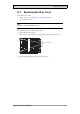
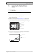
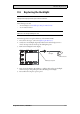
8.1 ModeSwitches
The iX Panel T100 has four mode switches (DIP switches) located on the rear side
of the operator panel.
1
24V DC
CF CARD
COM 1
RS422
RS485
COM 2
RS232
10/100
EXPANSION
BUSY
MODE
1 2 3 4
ON DIP
MODE
1 2 3 4
ON DIP
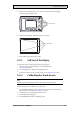
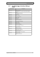
Warning:
Themodesbelowaretobeusedwithcaution.
Themodeswitcheshavethefollowingfunctions: 1=ON,0=OFF
Each letter in “MODE” has a corresponding mode switch.
MODE Description
0000 “Runmode”-bootsCE,normaloperation.
0010 SystemRestore,resetsthefilesystemandregistry,
reinstallsthesystemprogram(OPsys_bxxx.CA B).Restores
theoperatorpaneltofactorysettings.
Warning! Informationcaneasilyaccidentlybelost.
0100 ImageLoadmode(Sysload)allowsupgradingofthe
firmwareintheoperatorpanel.
Note: Allfilesincludingthefilesystemintheo perator
panelwillbedeletedwhenupgradingwithImageLoader.
1000 ServiceMenumode,theservicemenuforthesystem
programisshown. AllowstheusertosetIPconfiguration,
erasetheproject,calibratethetouchscreenetc. See
sectionServiceMenufordetails.
BeijerElectronics, MAEN007
21