iX T10A Installation Manual MAEN017F, 2013-09 English
Foreword Installation manual for iX T10A Foreword All operator panels are developed to satisfy the demands of human-machine communication. Built-in functions such as displaying and controlling text, dynamic indication, time channels, alarm and recipe handling are included. The operator panel works primarily in an object-oriented way, making it easy to understand and use. Configuration is carried out on a PC using the iX Developer configuration tool.
Contents Contents 1 Safety Precautions ....................................................... 1.1 General ........................................................... 1.2 UL and cUL Installation ......................................... 1.3 During Installation .............................................. 1.4 During Use ....................................................... 1.5 Service and Maintenance ........................................ 1.6 Dismantling and Scrapping .................................
Safety Precautions 1 Safety Precautions Both the installer and the owner and/or operator of the operator panel must read and understand this installation manual. 1.1 • • • • • • • • • • • • • General Read the safety precautions carefully. Check the delivery for transportation damage. If damage is found, notify the supplier as soon as possible. Do not use the operator panel in an environment with high explosive hazards.
Safety Precautions • All devices have to be supplied by a Class 2 power supply. Warning: Do not disconnect equipment unless power has been removed or the area is known to be non-hazardous • For Canada also AVERTISSEMENT – AVANT DE DECONNECTER L’EQUIPEMENT, COUPER LE COURANT OUS’ASSURER QUE L‘EMPLACEMENT EST DESIGNE NON DANGEREUX. Warning: Only UL and cUL approved expansion units are allowed to be connected to the port designated “EXPANSION”. At the moment there are no such units evaluated or allowed.
Safety Precautions 1.3 During Installation • The operator panel is designed for stationary installation on a plane surface, where the following conditions are fulfilled: – no high explosive risks – no strong magnetic fields – no direct sunlight – no large, sudden temperature changes • • • • • Install the product according to the accompanying installation instructions. Ground the product according to the accompanying installation instructions. Only qualified personnel may install the operator panel.
Safety Precautions 1.7 • Appearance of Air in Touch Screen The layer structure of the touch screen contains air and in rare cases appearance of bubbles can arise. This is purely cosmetic and does not affect any functionality of the panel. The appearance can occur under certain environmental conditions such as temperature, humidity, and atmospheric pressure.
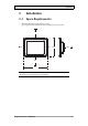
Installation 2 Installation 2.1 Space Requirements • • Maximum installation plate thickness: 8 mm Space requirements in millimeters when installing the operator panel: 100 50 50 228 100 100 280 Note: The dimensions on the drawing are not proportional.
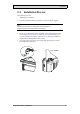
Installation 2.2 Installation Process The following is needed: • A Phillips/slot screwdriver 1. Unpack and check the delivery. If damage is found, notify the supplier. Note: Place the operator panel on a stable surface during installation. Dropping the panel or letting it fall may cause damage. 2. Use the cut out dimensions that are included on the outline drawing, found in section Operator Panel Drawings and in the Technical Data table, to cut a correct opening in the cabinet.
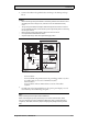
Installation 4. Connect the cables in the specified order, according to the drawing and steps below. Caution: • Ensure that the operator panel and the controller system have the same electrical grounding (reference voltage level), otherwise errors in communication may occur. • The operator panel must be brought to ambient temperature before it is started up. If condensation forms, ensure that the operator panel is dry before connecting it to the power outlet.
Installation 2.2.1 Connections to the Controller For information about the cables to be used when connecting the operator panel to the controller, please refer to the help file for the driver in question. 2.2.2 Other Connections and Peripherals Cables, peripheral equipment and accessories must be suitable for the application and its environment. For further details or recommendations, please refer to the supplier.
Technical Data 3 Technical Data Parameter iX T10A Front panel, W × H × D 280 × 228 × 7 mm Cut out dimensions, W×H 262 × 209 mm Mounting depth 44 mm (144 mm including clearance) Standalone mounting VESA 75 × 75 Note: Maximum screw length for VESA mounting is 4 mm. Usage of longer screws may lead to damage. Front panel seal IP 65 Rear panel seal IP 20 Touch screen material Polyester on glass, resistive. Overlay: Autoflex EBA 180L(1).
Technical Data Parameter iX T10A Power supply +24 V DC (18-32 V DC) CE: The power supply must conform with the requirements according to IEC 60950 and IEC 61558-2-4. UL and cUL: The power supply must conform with the requirements for class II power supplies. Display TFT-LCD with LED backlight. 640 × 480 pixels, 64 k colors Active area of display, W × H 211.2 × 158.
Chemical Resistance 4 Chemical Resistance 4.1 Metal Casing The frame and casing material is powder-coated aluminum.
Chemical Resistance 4.2 Touch Screen and Overlay 4.2.1 Autoflex EBA 180L Autoflex EBA 180L covers the overlay surrounding the touch screen.
Chemical Resistance 4.2.2 Touch Screen Surface The touch screen surface on the operator panel withstands exposure to the following solvents without visible change: Solvents Time Acetone 10 minutes Isopropanol 10 minutes Toluene 5 hours 4.2.3 Autoflex EBA 180L It is recommended to use the Autoflex EBA 180Ltouch display protection film, that can be ordered from Beijer Electronics.
Operator Panel Drawings 5 Operator Panel Drawings 5.1 Connectors COM 1/2 LAN COM 3/4 2 3 4 1 Pos. Connector Description 1 Power supply +24 V DC (18-32 V DC) 2 COM 1/2 Communication Ports 3 LAN 1 × 10/100 Base-T (shielded RJ-45) 4 COM 3/4 Communication Ports 5.
Operator Panel Drawings Note: Only iX T10A panels with part number 630000301 are equipped with terminated COM-ports.
Operator Panel Drawings 5.3 iX T10A Outline Ethernet COM3 RS232 / COM4 RS422/RS485 24 V DC COM1 RS232 / COM2 RS422/RS485 280 7 max. 8 mm 228 SD memory card slot 44 9 USB host 209 9 9 262 Expansion port 9 Note: A Step CAD file is available on the web site www.beijerelectronics.
Additional Installation Tips 6 Additional Installation Tips When experiencing communication problems in for example noisy environments or when operating close to temperature limits, the following recommendations are to be noticed. 6.
Additional Installation Tips Note: The grounding wires should be short and the conductor should have a large area. A long, thin grounding wire has a very high impedance (resistance) at high frequencies and will not guide disturbances to the ground. Multi-wire conductors are better than single wire conductors with the same area. A braided conductor wire with the same area is even better. The best is a short, thick grounding braid. 6.
Additional Installation Tips A good solution may be to use a shielded Ethernet cable, but to connect the shield at one end only. One option is to break the shield, see 3 in drawing above. A more elegant method is to expand the shielded Ethernet cabling with a piece of unshielded Ethernet cable, see 4 in drawing above. The shield can be grounded via an external 0.1 μF/250 V plastic capacitor, see 5 in drawing above. This will connect the HF transients to ground.
Additional Installation Tips 6.3 • • • • • • • • To Achieve Better EMC Protection Initially, use the original cabling from Beijer Electronics primarily. Use shielded cables for RS232 communication. Use twisted pair and shielded cabling for RS422 and RS485. Use the cabling intended for the bus type; Ethernet, Profibus, CC-Link, CAN, Device Net etc. Install and connect according to applicable specifications for the relevant bus standard.
Additional Installation Tips 6.4 Ambient Temperature The maximum ambient temperature for the operator panel is provided in the specifications. The ambient temperature refers to the temperature in the device cabinet which cools the operator panel’s electronics.
Additional Installation Tips 6.5 Safety Most of the operator panels are fed with 24 V DC. Power supply 230 V AC to 24 V DC Operator panel +24 V 1 0V 4 Power supply 230 V AC to 24 V DC Operator panel +24 V 2 0V 4 Distance? Power supply 230 V AC to 24 V DC Operator panel +24 V 3 0V 4 COM1 Small controller with expansion unit Ch0 Ch1 230 V AC COM100 Ch100 Ch101 5355 If a power supply that meets safety standards is used and only feeds the operator panel, there is no problem.
Additional Installation Tips 6.6 Galvanic Isolation Internal electronic Ethernet DC/DC galvanic isolation Filter DC/AC VCC +24 V DC CFL 0 V (GND) 0V 1.5 m RS422/485 RS232 USB USB The operator panel has galvanic isolation against the 24 V DC feed but no galvanic isolation between the communication ports for RS232, RS422/485 and USB. Only the Ethernet connection has galvanic isolation.
Additional Installation Tips 6.7 • • • Cable and Bus Termination RS485 If maximum transfer distance and maximum transfer speed is needed, shielded and twisted pair cable should be used. The mutual capacitance may not exceed 52.5 pF/m, and the cable area should be at least 0.25 mm2 (AWG 24). 0 V, the reference voltage for communication should be included in the cabling. With two-way communication use two pairs; one pair for communication and one pair for 0 V. The shield must be grounded at one end.
Head office Beijer Electronics AB Box 426 201 24 Malmö, Sweden www.beijerelectronics.