NA-9379 FnBus PIO N/A Specification FnIO S-Series: NA-9379 NA-9379 (FnIO Modbus Programmable I/O) PRELIMINARY Revision 1.
NA-9379 FnBus PIO N/A Specification Revision 1.02 Page 2 Table of Contents Table of Contents.............................................................................................................................................. 2 1.ENVIRONMENT SPECIFICATION............................................................................................................ 4 2.NA-9379 (FNIO MODBUS PROGRAMMABLE I/O)................................................................................. 5 2.1.
NA-9379 FnBus PIO N/A Specification Revision 1.02 Page 3 3.2.4.Adapter Information Special Register (0x1100, 4352)................................................................... 21 3.2.5.Adapter Setting Special Register (0x1600, 5632).......................................................................... 22 3.2.6.Expasion Slot Information Special Resister (0x2000, 8192).......................................................... 23 3.3.Surpported MODBUS Function Codes................................
NA-9379 FnBus PIO N/A Specification 1. ENVIRONMENT SPECIFICATION Environmental specification Operating Temperature Storage Temperature Relative Humidity Operating Altitude Mounting 0℃~55℃ -40℃~85℃ 5% ~ 90% non-condensing 2000m DIN rail General specification Shock Operating Vibration/shock resistance EMC resistance burst/ESD Installation Pos. / Protect. Class Product Certifications IEC 60068-2-6 Based on IEC 60068-2-6 Sine Vibration 10 ~ 25 Hz : 0.
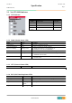
NA-9379 FnBus PIO N/A Specification Revision 1.02 2. NA-9379 (FNIO MODBUS PROGRAMMABLE I/O) 2.1. NA-9379 Specification Items Programmable Specification Specification Programming Program Memory Data Memory CoDeSys V3.
NA-9379 Revision 1.02 Specification FnBus PIO N/A Field Power Max. Current Field Power Contact Weight Module Size Environment Condition Page 6 System power I/O driver : Isolation Supply voltage : 24Vdc nominal Supply voltage range : 11~28.8Vdc DC 10A Max <165g 54mm x 99mm x 70mm Refer to ‘1. Environment Specification’ 2.2. NA-9379 Wiring Diagram Pin No. 0 2 4 6 Signal Description System Power 0V F.G Field Power 0V Field Power 24V Signal Description System Power 0V F.
NA-9379 Revision 1.02 Specification FnBus PIO N/A Page 7 2.3. NA-9379 LED Indicator 2.3.1. LED Indicator LED No. MOD NET RUN I/O Field Power LED Function / Description Module Status Not Used Error Status Expantion Module Status Field Power Enable LED Color Green/Red Green/Red Green/Red Green 2.3.2.
NA-9379 Specification FnBus PIO N/A Revision 1.02 Page 8 2.3.5. I/O LED (Expantion Module Status LED) Status Not Powered No Expansion Module FnBus On-line, Do not Exchanging I/O FnBus Connection, Run Exchanging I/O FnBus Connection Fault during Exchanging I/O LED is OFF To indicate Device has no expansion module or may not be powered. Flashing Green Green FnBus is normal but does not exchanging I/O data. (Passed the expantion module configuration) Exchanging I/O data.
NA-9379 Revision 1.02 Specification FnBus PIO N/A Page 9 2.4. NA-9379 Electrical Interface 2.4.1. RJ-45 Socket Shielded RJ-45 Socket RJ-45 1 2 3 4 5 6 7 8 Case Signal Name TD+ TDRD+ RDShield Description Transmit + Transmit Receive + Receive - 2.4.2. RS232/485 Port for MODBUS/RTU, Touch Pannel or IOGuide #5 GND #8 D#3 RXD #2 TXD #6 D+ Pin# 1 2 3 4 5 6 7 8 9 D-Sub 9Pin Signal Name Description TXD RS232 TXD RXD RS232 RXD GND RS232 GND D+ RS485 D+ DRS485 D- 2.4.3.
NA-9379 Specification FnBus PIO N/A Revision 1.02 Page 10 3. MODBUS/RTU INTERFACE (NOT TCP) 3.1.
NA-9379 Specification FnBus PIO N/A 3.1.2. Revision 1.02 Page 11 2 (0x02) Read Discrete Inputs This function code is used to read from 1 to 2000 contiguous status of discrete inputs in a remote device. The Request PDU specifies the starting address, i.e. the address of the first input specified, and the number of inputs. In the PDU Discrete Inputs are addressed starting at zero. Therefore Discrete inputs numbered 1-16 are addressed as 0-15.
NA-9379 Specification FnBus PIO N/A 3.1.4. Revision 1.02 Page 12 4 (0x04) Read Input Resgisters This function code is used to read from 1 to approx. 125 contiguous input registers in a remote device. The Request PDU specifies the starting register address and the number of registers. The register data in the response message are packed as two bytes per register, with the binary contents right justified within each byte.
NA-9379 Specification FnBus PIO N/A 3.1.6. Revision 1.02 Page 13 6 (0x06) Write Single Register This function code is used to write a single holding register in a remote device. Therefore register numbered 1 is addressed as 0. The normal response is an echo of the request, returned after the register contents have been written.
NA-9379 Specification FnBus PIO N/A 3.1.7. Revision 1.02 Page 14 8 (0x08) Diagnostics MODBUS function code 08 provides a series of tests for checking the communication system between a client ( Master) device and a server ( Slave), or for checking various internal error conditions within a server. The function uses a two–byte sub-function code field in the query to define the type of test to be performed. The server echoes both the function code and sub-function code in a normal response.
NA-9379 Revision 1.02 Specification FnBus PIO N/A Page 15 Sub-function 0x000B(11) Return Bus Message Count The response data field returns the quantity of messages that the remote device has detected on the communications system since its last restart, clear counters operation, or power–up.
NA-9379 Revision 1.02 Specification FnBus PIO N/A Page 16 Sub-function 0x0065(101) Return Slave Watchdog Error Count The response data field returns the quantity of watchdog error addressed to the remote device since its last restart, clear counters operation, or power–up.
NA-9379 Specification FnBus PIO N/A 3.1.9. Revision 1.02 Page 17 16 (0x10) Write Multiple Resgisters This function code is used to write a block of contiguous registers (1 to approx. 120 registers) in a remote device. The requested written values are specified in the request data field. Data is packed as two bytes per register. The normal response returns the function code, starting address, and quantity of registers written.
NA-9379 Specification FnBus PIO N/A Quantity of Write Hi Quantity of Write Lo Byte Count Write Reg. Value#0 Hi Write Reg. Value#0 Lo Write Reg. Value#1 Hi Write Reg. Value#1 Lo • Revision 1.02 Page 18 0x00 0x02 0x04 0x11 0x22 0x33 0x44 Response Field name Function Code Byte Count Read Reg. Value#0 Hi Read Reg. Value#0 Lo Read Reg. Value#1 Hi Read Reg.
NA-9379 Specification FnBus PIO N/A 08 Memory Parity Error 0A Gateway Unavailable Revision 1.02 Page 19 The server (or slave) attempted to read record file, but detected a parity error in the memory. The client (or master) can retry the request, but service may be required on the server (or slave) device.
NA-9379 Specification FnBus PIO N/A 3.2.1. Page 20 Adapter Resgister Mapping Address 0x0000~0x027F 0x0280~0x7FF 0x0800~0x0A7F 0x0A80~0x0FFF 0x1000~0x1FFF 0x2000~0x2FFF 0x4000~0x427F 3.2.2. Revision 1.
NA-9379 Specification FnBus PIO N/A 0x1022(4130) 0x1023(4131) Read Read/Write 1word 1word 0x1028(4136) Read 4word 3.2.4. Revision 1.02 Watchdog error counter, it is cleared by writing address 0x1020 Enable/disable auto recovery Watchdog error when receiving new frame. 0:Disable, 1:Enable(default). Its value is stored in EEPROM. I/O update time, Fnbus Process time, CoDeSys update time, CoDeSys Process Time.
NA-9379 Specification FnBus PIO N/A 3.2.5. Adapter Setting Special Register (0x1600, 5632) Address 0x1600(5632) 0x1602(5634) 0x1604(5636) 0x1606(5638) Access Read Read Read Read/Write Type, Size 2word 2word 2word 1word 0x1607(5639) Read/Write 1word 0x1608(5640) Read/Write 1word 0x1609(5641) Read/Write 1word 0x160A(5642) Read/Write 1word 0x160B(5643) Read/Write 1word 0x1610(5648) 0x1620(5664) Read Read/Write 3word 4word Description IP Address. (default : C0A8 6464 = 192.168.100.
NA-9379 Revision 1.02 Specification FnBus PIO N/A Page 23 **Modbus Station : This description for 0x160A register with bit. 3.2.6. Expasion Slot Information Special Resister (0x2000, 8192) Each expansion slot has 0x20(32) address offset and same information structure.
NA-9379 Specification FnBus PIO N/A + 0x17(+23) + 0x18(+24) + 0x19(+25) + 0x1A(+26) + 0x1B(+27) + 0x1C(+28) + 0x1D(+29) + 0x1E(+30) + 0x1F(+31) Revision 1.
NA-9379 Revision 1.02 Specification FnBus PIO N/A Page 25 Table 3.3.1.