
Manual


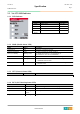


Table Of Contents
- Table of Contents
- 1. ENVIRONMENT SPECIFICATION
- 2. NA-9379 (FNIO MODBUS PROGRAMMABLE I/O)
- 3. MODBUS/RTU INTERFACE (NOT TCP)
- 3.1. Surpported MODBUS Function Codes
- 3.1.1. 1 (0x01) Read Coils
- 3.1.2. 2 (0x02) Read Discrete Inputs
- 3.1.3. 3 (0x03) Read Holding Resgisters
- 3.1.4. 4 (0x04) Read Input Resgisters
- 3.1.5. 5 (0x05) Write Single Coil
- 3.1.6. 6 (0x06) Write Single Register
- 3.1.7. 8 (0x08) Diagnostics
- 3.1.8. 15 (0x0F) Write Multiple Coils
- 3.1.9. 16 (0x10) Write Multiple Resgisters
- 3.1.10. 23 (0x17) Read/Write Multiple Resgisters
- 3.1.11. Error Response
- 3.2. MODBUS Special Register Map
- 3.2.1. Adapter Resgister Mapping
- 3.2.2. Adapter Identification Special Resgister (0x1000, 4096)
- 3.2.3. Adapter Watchdog Time, other Time Special Register (0x1020, 4128)
- 3.2.4. Adapter Information Special Register (0x1100, 4352)
- 3.2.5. Adapter Setting Special Register (0x1600, 5632)
- 3.2.6. Expasion Slot Information Special Resister (0x2000, 8192)
- 3.3. Surpported MODBUS Function Codes
- 3.1. Surpported MODBUS Function Codes

NA-9379
Specification
Revision 1.02
FnBus PIO N/A
Page 10
3. MODBUS/RTU INTERFACE (NOT TCP)
3.1. Surpported MODBUS Function Codes
Function
Code
Function Description
1(0x01) Read Coils Read output bit
2(0x02) Read Discrete Inputs Read input bit
3(0x03) Read Holding Registers Read output word
4(0x04) Read Input Registers Read input word
5(0x05) Write Single Coil Write one bit output
6(0x06) Write Single Register Write one word output
8(0x08) Diagnostics Read diagnostic register
15(0x0F) Write Multiple Coils Write a number of output bits
16(0x10) Write Multiple registers Write a number of output words
23(0x17) Read/Write Multiple registers Read a number of input words /Write a number of output words
– Refer to MODBUS APPLICATION PROTOCOL SPECIFICATION V1.1a
3.1.1. 1 (0x01) Read Coils
This function code is used to read from 1 to 2000 contiguous status of coils in a remote device. The Request PDU
specifies the starting address, i.e. the address of the first coil specified, and the number of coils. In the PDU Coils are
addressed starting at zero. Therefore coils numbered 1-16 are addressed as 0-15. The coils in the response message are
packed as one coil per bit of the data field. Status is indicated as 1= ON and 0= OFF.
• Request
Field name Example
Function Code 0x01
Starting Address Hi 0x10
Starting Address Lo 0x00
Quantity of Outputs Hi 0x00
Quantity of Outputs Lo 0x0A
• Response
Field name Example
Function Code 0x01
Byte Count 0x02
Output Status 0x55
Output Status 0x02
– In case of address 0x1015~0x1000 output bit value: 10101010_01010101.
PRELIMINARY