Ming Ji Intelligent Body Temperature Detection and Analysis System - Mini User Manual 0
All rights reserved. No part of this document may be copied, reproduced, or transmitted in any form or by any means without the written permission of the Company. Note: The products, services, or features purchased are subject to the company's commercial contract and its terms and conditions, and all or some of the products, services, or features described in this document may not be within the scope of the purchase or use.
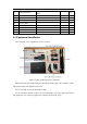
Contents 1. Preparation before Installation ................................................................................................ 1 1.1 Site survey ..................................................................................................................... 1 1.2 Equipment Preparation .................................................................................................. 1 2. Installation...........................................................................................
Blackbody Bluetooth Connection Failure ............................................................................... 26 5.3 Blackbody Battery Replace ......................................................................................... 28 5.4 Android System Language Setting .............................................................................. 29 5.5 FAQ .............................................................................................................................
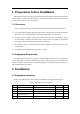
1. Preparation before Installation Ming Ji Mini is a temperature measurement device suitable for indoor environments and requires semi-coordination, which means the temperature results would be better if the tested person stand in front of the camera for at least 0.5 seconds. 1.1 Site survey To ensure the best performance, the following installation instructions should be followed.
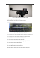
Dual-light Camera MegEye-TC1V-72DW-X3617 (INT) 1 Piece 7 Blackbody Meg-HT-02-01 1 Piece 8 Ethernet Cable 2 Piece 9 Camera Power Cable 1 Piece 10 Power Adapter 2 Piece 11 Screw Driver 1 Piece 12 Packing Box 1 Piece 13 Device Inner Lining 1 Set 14 Tripod 1 Piece 2.2 Equipment Installation After unpacking, all the equipment are shown as follows.
Figure 2-2 Dual-light camera and blackbody assembly Step 2: Dual-light camera and tripod assembly Fix the tripod adapter to the camera, then fix the camera to tripod. Step 3: Equipment connection Figure 2-3 Video analysis host port description 1) Use network cable to connect visible light camera to LAN port of video analysis host. 2) Use network cable to connect computer to WAN port of video analysis host. 3) Use a HDMI cable to connect monitor to video analysis host.
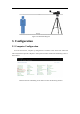
Figure 2-4 Installation diagram 3. Configuration 3.1 Computer Configuration To access the software, computer ip configuration is needed to ensure in the same LAN with video analysis host.
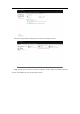
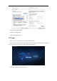
Click the Change Adaptor Settings button to enter the following interface: Right-click the local connection and click ‘Properties’ button, double-click Internet Protocol Version 4 (TCP IPV4) to enter the following interface:
Input the following IP address: IP address: 192.168.1.200 Subnet mask: 255.255.255.0 3.2 Login Note: Please use Chrome browser to login to Ming Ji system. Open Chrome browser and enter the IP address of video analysis host (192.168.1.9 by default) to enter login interface. Username is admin, password is admin123. After login, the homepage shows as below.
In this page, the visible-light video is shown on the left side and IR video on the right. 3.3 Dual-light alignment Click System Configuration->Algorithm->Dual-light alignment to align visible light and infrared light. Figure 3-1 Dual-light alignment page Ask someone to stand in front of the camera, drag the position and adjust the size of infrared picture, to completely overlap the imaging picture in visible light camera and infrared camera.
Figure 3-2 Dual-light alignment 3.4 Blackbody Angle Adjustment Blackbody is a calibration device and a standard temperature source, and IR camera performs real-time calibration based on blackbody temperature. In the infrared imaging, there is a blackbody box, which should be completely covered by the imaging of blackbody.
Figure 3-4 Blackbody angle adjustment 4. Software Functions 4.1 Real-time Surveillance 1. Real-time statistics of today's visitors. 2. Real-time statistics of today’s alarms, including: high temperature alarm, whitelist alarm, and no mask alarm. 3. Real-time captured image display. 4. Real-time alarm display.
4.2 System Configuration 4.2.1 Network Service 4.2.1.1 Network 1. General configuration IP configuration of video analysis box: support DHCP and static IP settings. The default IP address is 192.168.1.9. 2. HTTPS Certificate import This function is used to upload HTTPS certificate to the system. 4.2.1.2 Time The NTP server is used to synchronize time from a NTP server to video analysis host automatically. Manual timing is used to configure the time of video analysis host manually.
4.2.1.3 RTSP Broadcast 4.2.2 Camera Management Click ‘edit’ button to enter ‘edit camera’ page.
Click the drop-down box of ‘deployed face library’ and select face library, and save. Then once the person in the selected whitelist appears in the camera, he will be recognized, and the system sends out a whitelist alarm. 4.2.3 Firmware Note that if there is no special need, please do not change the factory default settings. 4.2.3.1 General configuration In this page, user can turn on or off the sound of whitelist alarm, body temperature and no mask alarm sound.
User can customize the sound of temperature alarm, click to upload a local audio file. 4.2.3.2 Bluetooth settings Current address: displays the current MAC address of the Bluetooth device. For example, A4:C1:38:7B:16:93. Update address: Enter the Bluetooth mac address to be updated. 4.2.3.3 Advanced setting Background image quality: default value is 20.
4.2.3.4 Watermark settings These parameters are used to configure the text format of watermark. 4.2.4 Algorithm 4.2.4.1 General settings Capture mode: high quality mode and full capture mode. Push mode: background and captured image, Captured image only. Image pushing tactic: timed image pushing, Best quality pushing. Image push interval (seconds): 0.5s~4s. Image pushing count: 4, 5, 6, 7, 8, 9, 15, 20. Region of interest (ROI): configure the Region of interest of visible light camera.
Region of interest Configuration method of ROI: Click ‘view configuration’ button to open ‘ROI setting’ page. The button ‘Status’ is used to enable or disable ROI setting. Then double click to add vertex to draw a polygon as camera ROI. Then press ‘Confirm’ button on ‘ROI setting’ page and ‘Save’ button on ‘Algorithm Configuration’ page to take effect. 4.2.4.2 Dual-light alignment Dual-light alignment is used to align visible light and infrared light, to get an accurate temperature.
overlap the imaging picture in visible light camera and infrared camera. Then drag blackbody box stay inside and near the boundary of infrared picture, and finally press ‘save’ button. 4.2.5 Library Management 4.2.5.1 Face Library 1) Face library management Click ‘face library management’ button to enter the face library management page, then all the existed face libraries will be shown here. Click ‘new library’ button to create a new library.
1. Supports ZIP or TAR format, the size should not exceed 1GB, and the number of photo should not exceed 50,000. 2. Supports PNG, JPG and BMP images, and the size of a single image should not exceed 4MB. 3. Click the select library drop-down box, select the library to be imported, drag the compressed file into this area, and click the save button. Note: 1. The same person can only exist in one library, and two libraries cannot be imported at the same time. 2.
4) Library reset Click the bottom library reset button to delete all library information. 5) Search in the library Support selection of library, and search by name and remark. 4.2.5.2 List of Failures Display a list of images that failed to be imported, including name, image, cause of error, remarks, time created and operation. Supports single deletion, batch deletion and clear all. Click the batch delete button and select the failed information to be deleted.
4.2.6 Device Management 4.2.6.1 Log Management Click the log management button, select the type of log to be exported, and click ‘save’ button , then click ‘download log’ button to download. 4.2.6.2 User Management 1) Change password Manually enter the original password, new password, and confirm password, and click ‘save’ button to complete the password modification. The default password of the system is admin123.
4.2.6.3 Timed Reboot Click the enable button, select the restart date and time, and click ‘save configuration’ button to create a scheduled device restart schedule. 4.2.6.4 Device Maintenance Click ‘reboot’ button, then the device will restart immediately. Click ‘Factory Reset’ button to restore all configurations to default factory configuration. Please use this feature with caution. 1) Local upgrade Get the software package from MEGVII technical support team.
2) Device maintenance View the device information of current device 3) Version information View the software version, firmware version, algorithm version, and algorithm model of the current device.
4.3 History Search 4.3.1 Alarm History Alarm history search: select alarm type, library, name or remark and time. Alarm types includes face recognition, body temperature and no mask. Export: click the ‘export’ drop-box to select file type ‘Excel’ or ‘CSV’, then the alarm history will be exported into a compressed file. Each compressed file size is less than 4GB. Clear historical Records: click this button to clear all the alarm history. 4.3.
capture history will be exported into a compressed file. Each compressed file size is less than 4GB. Clear record: click this button to clear all capture records. 5. FAQ and Troubleshooting 5.1 Visible Light Camera Setting Note: This method is only applicable to Windows OS computer, and make sure the IE version is above 6.0. If you use a non-IE browser or do not allow the IE browser running ActiveX to access the WEB management interface, you cannot modify the configuration and view the video stream.
Step 4: Enter the IP address (193.169.2.9) of the camera in the address bar, such as 193.169.2.9. If the computer uses this camera for the first time, a prompt to download the plug-in interface will appear. Download and install the plug-in. After the installation is completed, restart the IE browser and enter the camera IP address.
null. Camera settings Set time zone and time. On the WEB management interface, click [Device Configuration] -> [Settings] -> [General] in the navigation bar to set the time zone and time. After configuration, click OK. Configure IP address. On the WEB management interface, click [Device Configuration] -> [Settings] -> [Network] in the navigation bar to configure the network. After configuration, click OK.
Set camera parameters. On the WEB management interface, click [Device Configuration] -> [Settings] -> [Camera Parameters] in the navigation bar to configure camera parameters. After configuring, click OK. For backlighting scenario, you can set the BLC and DWDR to “Open” to get a better image. 5.2 Blackbody Bluetooth Connection Failure First, confirm the Bluetooth antenna is connected.
the mouse to return to app page. Left click “PairManager” to search all the available blackbody, then the results will be listed with MAC address. Left click “解绑蓝牙” to unbind Bluetooth. Choose the correct address shown on the label posted on the bottom of blackbody, and double left click to bind.
In System Configuration->Firmware->Bluetooth setting, user can see the current bound Bluetooth. 5.3 Blackbody Battery Replace On the top and bottom of blackbody, there are two screw holes. Use a screwdriver to remove the screw. Then remove the battery cover to replace new battery. Only one 2032 button battery is needed for each blackbody.
5.4 Android System Language Setting Connect a mouse, monitor with HDMI cable to the host. Right click the mouse to return to app page. Click Setting->Languages & input -> Languages -> Add a language, and select a language in the list, then drag the sort icon of the selected langue to the top, and it will take effect immediately.
5.5 FAQ 1. Q: Why some people only have captured images but without any measured temperature? A: Because the face appears outside the IR imaging and inside visible light imaging, so the system cannot measure temperature. Configure a ROI in the area of IR imaging for visible light camera. 2.
A: Most probably because the cable between aperture to camera is not correctly connected. This cable should be connected from top to bottom. Figure 5-1 Failure of visible light camera Figure 5-2 Correct connection of cable between aperture to camera Note:Please take attention that changes or modification not expressly approved by the party responsible for compliance could void the user’s authority to operate the equipment. This device complies with Part 15 of the FCC Rules.