
User's Manual

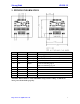
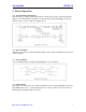
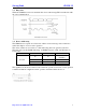
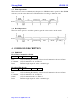

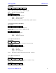
Table Of Contents
- Main Features
- PINNING INFORMATION
- Device Operation
- Command Description
- 4-2. Command Overview
- 4-3. Command List
- 4-3-1. Select Mifare card
- 4-3-2. Login to a sector
- 4-3-3. Download Key into SL030
- 4-3-4. Login sector via stored key
- 4-3-5. Read a data block
- 4-3-6. Write a data block
- 4-3-7. Read a value block
- 4-3-8. Initialize a value block
- 4-3-9. Write master key (KeyA)
- 4-3-10. Increment value
- 4-3-11. Decrement value
- 4-3-12. Copy value
- 4-3-13. Read a data page (UltraLight & NTAG203)
- 4-3-14. Write a data Page (UltraLight & NTAG203)
- 4-3-15. Request for Answer to Select (ISO14443-4)
- 4-3-16. Exchange Transparent Data (T = CL)
- 4-3-17. LED Control
- 4-3-18. Power Down
- 4-3-19. Write Perso
- 4-3-20. Commit Perso
- 4-3-21. Get firmware version
- 4-3-22. Turn on/off Auto-detection
- 4-3. Command List
- Differences from previous version

StrongLink SL030 3.1
http://www.stronglink-rfid.com
7
3-7. Write Operations
The host device send a command(refer chapter 4) to SL030 via write operation, then SL030
will carry out the order that receive. Finished time according to different order
3-8. Read Operations
The host device passes to read the operation gets the order carries out the result
4. COMMAND DESCRIPTION
4-1. FORMAT
Host Write Command to SL030:
Address
Len
Command
Data
Address: 1 byte, 0xA0
Len: 1 byte indicating the number of bytes from Command to the end of Data
Command: 1 byte Command code, see Table 3
Data: Variable length depends on the command type
Host Read The Result:
Address
Len
Command
Status
Data
Address: 1 byte, 0xA1
Len: 1 byte indicating the number of bytes from Command to the end of Data
Command: 1 byte Command code, see Table 3
Status: 1 byte Command status, see Table 4
Data: Variable length depends on the command type.