EN - english Instructions for installation and operation Data Display DD109
Dear customer, Thank you very much for deciding in favour of the data display DD109. Please read this installation and operation manual carefully before mounting and initiating the device and follow our advice. A riskless operation and a correct functioning of the data display are only guaranteed in case of careful observation of the described instructions and notes. Headquarter : / China France BEKO TECHNOLOGIES S.a.r.l. Deutschland / Germany BEKO TECHNOLOGIES (Shanghai) Co. Ltd.
Table of contents 1 2 3 4 5 6 7 8 9 10 10.1 10.2 11 11.1 11.2 12 12.1 13 13.1 14 14.1 14.1.1 14.2 14.2.1 14.3 14.3.1 14.3.2 14.4 14.5 14.5.1 14.5.2 14.5.3 14.5.
Safety instructions 1 Safety instructions Please check whether this manual corresponds with the instruments type. Please observe all notes indicated in this instruction manual. It contains essential information which have to be observed during installation, operation and maintenance. Therefore this instruction manual has to be read categorically by the technician as well as by the responsible user / qualified personnel before installation, initiation and maintenance.
Safety instructions Further safety instructions: • Also the applicable national regulations and safety instructions have to be observed during installation and operation. • The data display is not allowed to be used in explosive areas. Additional remarks: • Do not overheat the instrument! Attention ! Malfunctions at the data display Faulty installation and insufficient maintenance may lead to malfunctions of the data display which may affect the measuring results and which may lead to misinterpretations.
Field of application 2 Field of application • • • The data display is a stationary display instrument with data logger e. g. for corresponding consumption and dew point sensors (please see "Technical data") The data display is used e. g. in the following applications Flow station Dew point set For functioning, the data display requires an operating voltage (see Technical data).
Technical data 5 Technical data Dimensions wall housing Dimensions: 4.65“ x 4.53“ x 3.66“ Dimensions panel mounting Dimensions: 3.62“ x 3.62“ Housing material ABS synthetic material Protection type housing IP 65 Operating temperature 0… 122°F Transportation temperature -4… 158 °F Sensor inputs 2 inputs for dew point and consumption sensors (optional 2 analogue inputs) Interface USB Keypad 4 keys Power supply 100 .
Dimensions 6 Dimensions Dimensions wall housing 118,0 mm = 4,65“ 92,0 mm = 3,62“ 115,0 mm = 4,53“ 107,5 mm = 4,23“ 133,0 mm = 5,24“ 25,0 mm = 0,98“ 20,0 mm = 0,79“ Dimensions for panel mounting 118,0 mm = 4,65“ 115,0 mm = 4,53“ 13,5 mm = 0,53“ 98,5 mm = 3,88“ 70,0 mm = 2,76“ 91,7 mm = 3,61“ 8,0 mm = 0,31“ 92,0 mm = 3,62“ 8 Data Display DD109
Mounting 7 Mounting Mounting wall housing: The cables for sensors and for the power supply are already wired at DD10: • Do not connect mains cable to the power line • Release the 4 screws at the front housing • Remove plug from the reverse side of the front housing • Drill holes into the wall according to the given grid dimension (please see drawing) • Mount wall housing (anchor and screws included in the scope of delivery) • Attach again plug for the power supply and for the sensors • Insert the front ho
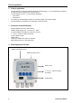
Plug reverse side 8 Plug reverse side Supply: 2 AWG12 – AWG24, cable cross-sections: 0.2 ... 2.5 mm Signals: 2 AWG16 ... AWG28, cable cross-sections: 0.14 ... 1.5 mm 9 Connecting diagram reverse side Wiring scheme reverse side data display: A: Alarm 1 B: Alarm 2 C: Power supply D: no use E: optional F: optional G: Flow sensor H: Galvanically separated pulse output flow sensor I: DPsensor Important information: Please make sure that the configuration you ordered has been matched with the sensors.
Analogue current signal 10.2 Alarm connection NC and COM are closed in case of: - alarm - power failure - sensor break 11 Analogue current signal The flow sensor and the DP sensor offer the possibility to provide the measured values as analogue current signal 4…20 mA for further process treatment . The connection schemes have already been set for this. 11.
Galvanic isolated pulse output 12 Galvanic isolated pulse output A galvanic isolated pulse output is available for the flow sensor. It deals with a semi-conductor relay which is galvanic isolated from the supply voltage by means of optoelectronic couplers. Maximum switching capacity : Umax: 32V, Imax: 20 mA 12.1 Connecting diagram pulse output flow sensor Pulse counter flow sensor to terminal H clamps 1 and 2 13 Connection pulse: active high active high 13.
Operation 14 Operation The measured values will be indicated page by page. Depending on the sensor and the settings one or several values can be indicated on one display page. These settings can be changed via the optional software or - on request - by BEKO TECHNOLOGIES. 14.1 Description of the display icons Status display Indication of measured value: Only one page of measured values will be shown at a time.
Operation 14.2 Operation of the main keys 14.2.1 Concept for key operation - 4.0 °Ftd • use these keys to browse and select different items in the menu and scroll through different pages of measurement values • use these keys to alter or adjust the setting option or numbering Back Enter 14.
Operation 14.3.1 Selection fields • Options for selection of the parameters - Selection field for deselected point - Selection field for selected point • Selection of the selection field via the "arrow up“ and "arrow down“ keys • By means of the "Enter“key the selected option can be activated • Leaving the menu point: Use the "Back“ key to get back to the last menu level without activating the selected option 14.3.
Operation 14.5 Main menu points The data display is supplied with standard settings. Main menu points in the data display: • Logger operation • Set Alarm 1 • Set Alarm 2 • Sensor setting • Communication settings (Option BUS systems) • System status and setting 14.5.1 Logger operation Set logging rate Set storage interval and average value determination The storage interval defines the time interval in which the data should be recorded. One value is recorded of each activated channel.
Scope of delivery 14.5.2 Alarm settings It is possible to set 2 individual alarm thresholds: 1. “Set Alarm 1 threshold” 2. ”Set Alarm 2 threshold” In this example the sensor is connected to terminal I. „Type: High" means: The alarm is triggered if the value is higher than the threshold. If the alarm is exceeded or dropped below the background becomes red resp. starts blinking. The factory setting of the hysteresis is 35°F td.
Conformity declaration 16 Conformity declaration 18 Data Display DD109
Conformity declaration BEKO TECHNOLOGIES GMBH 41468 Neuss, GERMANY Phone: +49 2131 988-0 www.beko.
A L Active high ..........................................................12 Active low............................................................12 Alarm 1 (pre-alarm) ............................................13 Alarm 1 exceeded...............................................13 Alarm 1 undercut ................................................13 Alarm 2 (main alarm) ..........................................13 Alarm connection................................................
Conformity declaration Data Display DD109 21
Data Display DD109
Conformity declaration Data Display DD109 23
Technical changes and errors excepted.