BK 5200 BK 6300 Split Air Conditioner User Manual
Content Operation Notices Precautions............................................................................................................1 Parts name ............................................................................................................2 Screen Operation Guide Buttons on remote controller .................................................................................3 Introduction for icons on display screen ................................................................
Precautions Warning cause electric shock. may be broken. damage. Please contact dealer when you need to repair air conditioner. person can perform the work. Otherwise, it may cause personal injury or damage. damage or personal injury. personal injury or damage. electric shock. Otherwise, it may cause personal injury or damage. Working temperature range Maximum cooling Minimum heating 18 ~43 Indoor side DB/WB( 32/23 20/- ; for heat pump unit is -7 ~ 43 1 ) .
Parts name Indoor Unit air inlet panel ¿OWHU aux.button KRUL]RQWDO ORXYHU cooling indicator power indicator air outlet receiver window display heating indicator temp. indicator drying indicator (Display content or position may be different from above graphics, please refer to actual products) remote control Outdoor Unit air inlet Connection wire air outlet Notice: $FWXDO SURGXFW PD\ EH GLIIHUHQW IURP DERYH JUDSKLFV SOHDVH UHIHU WR DFWXDO products.
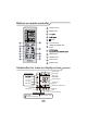
Buttons on remote controller 1 ON/OFF button 2 MODE button 3 4 5 2 1 3 4 button 6 CLOCK button 7 TIMER ON/TIMER OFF button 5 8 6 8 7 10 9 12 11 9 TEMP button 10 TURBO button 11 LIGHT button 12 SLEEP button Introduction for icons on display screen Set fan speed Send signal Operation mode Cool mode Dry mode Set temperature Fan mode Turbo mode Set time Heat mode TIMER ON / TIMER OFF Clock Child lock Light Up & down swing Sleep mode Temp. display type :Set temp. :Indoor ambient temp.
Introduction for buttons on remote controller Note: Ɣ $IWHU SXWWLQJ WKURXJK WKH SRZHU WKH DLU FRQGLWLRQHU ZLOO JLYH RXW D VRXQG 2SHUDWLRQ LQGLFWRU LV 21 UHG LQGLFDWRU $IWHU WKDW \RX FDQ RSHUDWH WKH DLU conditioner by using remote controller.
Introduction for buttons on remote controller 3 EXWWRQ Ɣ 3UHVV RU EXWWRQ RQFH LQFUHDVH RU GHFUHDVH VHW WHPSHUDWXUH ć . +ROGLQJ RU EXWWRQ V ODWHU VHW WHPSHUDWXUH RQ UHPRWH FRQWUROOHU ZLOO FKDQJH TXLFNO\ 2Q UHOHDVLQJ EXWWRQ DIWHU VHWWLQJ LV ¿QLVKHG WHPSHUDWXUH LQGLFD WRU RQ LQGRRU XQLW ZLOO FKDQJH DFFRUGLQJO\ 7HPSHUDWXUH FDQ¶W EH DGMXVWHG XQGHU auto mode) Ɣ :KHQ VHWWLQJ 7,0(5 21 7,0(5 2)) RU &/2&. SUHVV RU EXWWRQ WR adjust time.
Introduction for buttons on remote controller 6 CLOCK button Press this button to set clock time. " " icon on remote controller will blink. Press RU EXWWRQ ZLWKLQ V WR VHW FORFN WLPH (DFK SUHVVLQJ RI RU EXWWRQ FORFN WLPH ZLOO LQFUHDVH RU GHFUHDVH PLQXWH ,I KROG RU EXWWRQ V ODWHU WLPH ZLOO change quickly. Release this button when reaching your required time. Press &/2&.
Introduction for buttons on remote controller 8 ; )$1 EXWWRQ 3UHVV WKLV EXWWRQ XQGHU FRRO DQG GU\ PRGH WR VWDUW XS [ IDQ IXQFWLRQ DQG LFRQ RQ UHPRWH FRQWUROOHU ZLOO EH GLVSOD\HG 3UHVV WKLV EXWWRQ DJDLQ WR FDQFHO [ IDQ function, and " "icon will disappear. Note: Ɣ :KHQ [ IDQ IXQFWLRQ LV RQ LI WKH DLU FRQGLWLRQHU LV WXUQHG RII LQGRRU IDQ ZLOO VWLOO operate at low speed for a while to blow the residual water inside the air duct.
Introduction for buttons on remote controller 11 SLEEP button 8QGHU &22/ +($7 RU '5< PRGH SUHVV WKLV EXWWRQ WR VWDUW XS VOHHS IXQFWLRQ " " icon is displayed on remote controller. Press this button again to cancel sleep function and " " icon will disappear. 12 LIGHT button Press this button to turn off display light on indoor unit. " " icon on remote controller disappears. Press this button again to turn on display light. " " icon is displayed.
Operation guide 1. $IWHU SXWWLQJ WKURXJK WKH SRZHU SUHVV 21 2)) EXWWRQ RQ UHPRWH FRQWUROOHU WR turn on the air conditioner. 2. 3UHVV 02'( EXWWRQ WR VHOHFW \RXU UHTXLUHG PRGH $872 &22/ '5< )$1 +($7 3. 3UHVV RU EXWWRQ WR VHW \RXU UHTXLUHG WHPSHUDWXUH 7HPSHUDWXUH FDQ¶W EH adjusted under auto mode). 4. 3UHVV )$1 EXWWRQ WR VHW \RXU UHTXLUHG IDQ VSHHG DXWR ORZ PHGLXP DQG KLJK speed. 5. Press " " button to select fan blowing angle. Replacement of batteries in remote controller 1.
Emergency operation If remote controller is lost or damaged, please use auxiliary button to turn on or turn off the air conditioner. The operation in details are as below: $V VKRZQ LQ WKH ¿J 2SHQ SDQHO SUHVV DX[ EXWWRQ WR WXUQ RQ RU WXUQ RII WKH air conditioner. When the air conditioner is turned on, it will operate under auto mode. panel aux. button Clean and maintenance Note: Ŷ 7XUQ RII WKH DLU FRQGLWLRQHU DQG GLVFRQQHFW WKH SRZHU EHIRUH FOHDQLQJ WKH DLU conditioner to avoid electric shock.
Clean and maintenance &OHDQ ¿OWHU 1 Open panel 2 5HPRYH ¿OWHU &OHDQ ¿OWHU 3 Pull out the panel to a certain DQJOH DV VKRZQ LQ WKH ¿J 5HPRYH WKH ¿OWHU DV LQ GLFDWHG LQ WKH ¿J 4 Ɣ 8VH GXVW FDWFKHU RU ZDWHU WR FOHDQ WKH ¿OWHU Ɣ :KHQ WKH ¿OWHU LV YHU\ GLUW\ XVH the water (below 45ć ) to clean it, and then put it in a shady and cool place to dry. ,QVWDOO ¿OWHU ,QVWDOO WKH ¿OWHU DQG WKHQ FORVH WKH panel cover tightly.
Clean and maintenance Checking before use-season 1. Check whether air inlets and air outlets are blocked. 2. Check whether circuit break, plug and socket are in good condition. &KHFN ZKHWKHU ¿OWHU LV FOHDQ 4. Check whether mounting bracket for outdoor unit is damaged or corroded. If yes, please contact dealer. 5. Check whether drainage pipe is damaged. Checking after use-season 1. Disconnect power supply. &OHDQ ¿OWHU DQG LQGRRU XQLW¶V SDQHO 3.
Malfunction analysis General phenomenon analysis Please check below items before asking for maintenance. If the malfunction still FDQ¶W EH HOLPLQDWHG SOHDVH FRQWDFW ORFDO GHDOHU RU TXDOL¿HG SURIHVVLRQDOV Phenomenon Check items Solution Ɣ :KHWKHU LW V LQWHUIHUHG VHYHUHO\ Ɣ 3XOO RXW WKH SOXJ 5HLQVHUW (such as static electricity,stable the plug after about 3min, and voltage)? then turn on the unit again. Indoor unit FDQ¶W UHFHLYH remote FRQWUROOHU¶V signal or remote controller has no action.
Malfunction analysis Phenomenon $LU FRQGLW LRQHU FDQ¶W operate Check items Solution Ɣ 3RZHU IDLOXUH" Ɣ :DLW XQWLO SRZHU UHFRYHU\ Ɣ ,V SOXJ ORRVH" Ɣ 5HLQVHUW WKH SOXJ Ɣ &LUFXLW EUHDN WULSV RII RU fuse is burnt out? Ɣ $VN SURIHVVLRQDO WR UHSODFH circuit break or fuse. Ɣ :LULQJ KDV PDOIXQFWLRQ" Ɣ $VN SURIHVVLRQDO WR UHSODFH LW Ɣ 8QLW KDV UHVWDUWHG LPPHGLDWHO\ Ɣ :DLW IRU PLQ DQG WKHQ WXUQ after stopping operation? on the unit again.
Malfunction analysis Phenomenon Check items Solution Odours are emitted Ɣ :KHWKHU WKHUH¶V RGRXU VRXUFH Ɣ (OLPLQDWH WKH RGRXU VRXUFH such as furniture and cigarette, Ɣ &OHDQ WKH ¿OWHU etc. $LU FRQGLWLR ner operates abnormally Ɣ :KHWKHU WKHUH¶V LQWHUIHUHQFH such as thunder, wireless devices, etc. Ɣ 'LVFRQQHFW SRZHU SXW EDFN power, and then turn on the unit again.
Malfunction analysis Error Code Ɣ :KHQ DLU FRQGLWLRQHU VWDWXV LV DEQRUPDO WHPSHUDWXUH LQGLFDWRU RQ LQGRRU XQLW ZLOO EOLQN WR GLVSOD\ FRUUHVSRQGLQJ HUURU FRGH 3OHDVH UHIHU WR EHORZ OLVW IRU LGHQWL¿F ation of error code. $ERYH LQGLFDWRU GLDJUDP LV RQO\ Indoor for reference. Please refer to display actual product for the actual indicator and position. Error code Error code Troubleshooting H1 0HDQV GHIURVWLQJ VWDWXV ,W¶V WKH QRUPDO SKHQRPHQRQ E5 It can be eliminated after restarting the unit.
$W OHDVW FP Space to the ceiling Installation dimension diagram Space to the wall $W OHDVW FP $W OHDVW FP OHD $W o et the n tio uc tr bs o the to n e ac ctio Sp stru W ob DV OH W $ cm 30 $W OHDVW FP Space to the obstruction ac Sp $W OHDVW FP FP VW 6SDFH WR WKH ÀRRU Space to the wall $W OHDVW F P Space to th e wall n tio c tru s ce a Sp t he ot ob W DV OH $W $W OHDVW FP P F Space to the obstruction Drainage pipe 17
Tools for installation 1 Level meter 2 Screw driver 3 Impact drill 4 Drill head 5 Pipe expander 6 Torque wrench 7 Open-end wrench 8 Pipe cutter 9 Leakage detector 10 Vacuum pump 11 Pressure meter 8QLYHUVDO PHWHU 13 Inner hexagon spanner Note: 14 Measuring tape Ɣ 3OHDVH FRQWDFW WKH ORFDO DJHQW IRU LQVWDOODWLRQ Ɣ 'RQ W XVH XQTXDOL¿HG SRZHU FRUG Selection of installation location Basic requirement Installing the unit in the following places maycause malfunction.
Requirements for electric connection Safety precaution 1. Must follow the electric safety regulations when installing the unit. $FFRUGLQJ WR WKH ORFDO VDIHW\ UHJXODWLRQV XVH TXDOL¿HG SRZHU VXSSO\ FLUFXLW DQG circuit break. 3. Make sure the power supply matches with the requirement of air conditioner. 8QVWDEOH SRZHU VXSSO\ RU LQFRUUHFW ZLULQJ RU PDOIXQFWLRQ 3OHDVH LQVWDOO SURSHU power supply cables before using the air conditioner. 4.
Installation of indoor unit Step one: choosing installation location 5HFRPPHQG WKH LQVWDOODWLRQ ORFDWLRQ WR WKH FOLHQW DQG WKHQ FRQ¿UP LW ZLWK WKH FOLHQW Step two: install wall-mounting frame +DQJ WKH ZDOO PRXQWLQJ IUDPH RQ WKH ZDOO DGMXVW LW LQ KRUL]RQWDO SRVLWLRQ ZLWK WKH OHYHO PHWHU DQG WKHQ SRLQW RXW WKH VFUHZ ¿[LQJ KROHV RQ WKH ZDOO 'ULOO WKH VFUHZ ¿[LQJ KROHV RQ WKH ZDOO ZLWK LPSDFW GULOO WKH VSHFL¿FDWLRQ RI GULOO KHDG VKRXOG EH WKH VDPH DV WKH SODVWLF H[SDQVLRQ SDUWLFOH DQG WKHQ
Installation of indoor unit Indoor Note: Ɣ 3D\ DWWHQWLRQ WR GXVW SUHYHQWLRQ DQG WDNH UHOHYDQW VDIHW\ PHDVXUHV ZKHQ RSHQLQJ WKH KROH Ɣ 7KH SODVWLF H[SDQVLRQ SDUWLFOHV DUH QRW SURYLGHG DQG VKRXOG EH ERXJKW ORFDOO\ outdoor ĭ ĭ 5-10° Step four: outlet pipe 1. The pipe can be led out in the direction of right, rear right, left or rear left. 2. When select leading out the pipe from left or right, please cut off the corresponding hole on the bottom case.
Installation of indoor unit open-end wrench union nut torque wrench pipe Hex nut diameter Tightening torque (N.m) 15~20 ĭ 30~40 ĭ 40~55 ĭ 60~65 ĭ 70~75 ĭ indoor pipe 4. Wrap the indoor pipe and joint of connection pipe with insulating pipe, and then wrap it with tape. insulating pipe Step six: install drain hose 1. Connect the drain hose to the outlet pipe of indoor unit. drain hose outlet pipe 2. Bind the joint with tape.
Installation of indoor unit 2. Make the power connection wire go through the cable-cross hole at the back of indoor unit and then pull it out from the front side. cable-cross hole power connection wire 3. Remove the wire clip; connect the power connection wire to the wiring terminal DFFRUGLQJ WR WKH FRORU WLJKWHQ WKH VFUHZ DQG WKHQ ¿[ WKH SRZHU FRQQHFWLRQ ZLUH with wire clip. 18、24K Heat pump type: N(1) 2 3 blue black brown yellowgreen Outdoor unit connection 4.
Installation of indoor unit Step eight: bind up pipe 1. Bind up the connection pipe, power cord and drain hose with the band. connection pipe drain hose band indoor and outdoor power cord indoor unit gas pipe indoor power cord liquid pipe 3. Bind them evenly. 4. The liquid pipe and gas pipe should be bound separately at the end. band drain hose 2. Reserve a certain length of drain hose and power cord for installation when binding them.
Installation of outdoor unit 6WHS RQH ¿[ WKH VXSSRUW RI RXWGRRU XQLW (select it according to the actual installation situation) 1. Select installation location according to the house structure. 2. Fix the support of outdoor unit on the selected location with expansion screws. Note: Ɣ 7DNH VXI¿FLHQW SURWHFWLYH PHDVXUHV ZKHQ installing the outdoor unit. Ɣ Make sure the support can withstand at least four times of the unit weight.
Installation of outdoor unit Step four: connect indoor and outdoor pipes 3. Pretightening the union nut with hand. 1. Remove the screw on the right handle of outdoor unit and then remove the handle. pipe joint screw union nut handle 2. Remove the screw cap of valve and aim the pipe joint at the bellmouth of pipe. 4. Tighten the union nut with torque wrench by referring to the sheet below. torque Hex nut diameter Tightening (N.
Installation of outdoor unit 2. Fix the power connection wire and signal control wire with wire clip (only for cooling and heating unit). Note: Ɣ $IWHU WLJKWHQ WKH VFUHZ SXOO WKH SRZHU FRUG VOLJKWO\ WR FKHFN LI LW LV ¿UP Ɣ 1HYHU FXW WKH SRZHU FRQQHFWLRQ ZLUH WR SURORQJ RU VKRUWHQ WKH GLVWDQFH Step six: neaten the pipes 1. The pipes should be placed along the wall, bent reasonably and hidden possibly. Min. semidiameter of bending the pipe is 10cm. 2.
Vacuum pumping Use vacuum pump 1. Remove the valve caps on liquid valve the liquid valve and gas piezometer Lo Hi valve and the nut of refrigas valve gerant charging vent. refrigerant valve cap 2. Connect the charging hose charging vent RI SLH]RPHWHU WR WKH UHIUL gerant charging vent of gas nut of refrigerant valve and then connect the charging vent other charging hose to the vacuum pump vacuum pump.
Check after installation Ɣ &KHFN DFFRUGLQJ WR WKH IROORZLQJ UHTXLUHPHQW DIWHU ¿QLVKLQJ LQVWDOODWLRQ Items to be checked Possible malfunction +DV WKH XQLW EHHQ LQVWDOOHG ¿UPO\" The unit may drop, shake or emit noise. Have you done the refrigerant leakage test? ,W PD\ FDXVH LQVXI¿FLHQW FRROLQJ (heating) capacity. ,V KHDW LQVXODWLRQ RI SLSHOLQH VXI¿FLHQW" It may cause condensation and water dripping. Is water drained well? It may cause condensation and water dripping.
&RQ¿JXUDWLRQ RI FRQQHFWLRQ SLSH 1. Standard length of connection pipe Ɣ P P P 2.Min. length of connection pipe is 3m. 3.Max. length of connection pipe and max. high difference.
&RQ¿JXUDWLRQ RI FRQQHFWLRQ SLSH $GGLWLRQDO UHIULJHUDQW FKDUJLQJ DPRXQW IRU 5 5 & 5 $ DQG 5 D Diameter of connection pipe Outdoor unit throttle Cooling only(g/m) Cooling and heating(g/m) Liquid pipe(mm) Gas pipe(mm) ĭ ĭ RU ĭ 15 20 ĭ RU ĭ ĭ RU ĭ 15 50 ĭ ĭ RU ĭ 30 120 ĭ ĭ RU ĭ 60 120 ĭ _ 250 250 ĭ _ 350 350 31
Pipe expanding method Note: Improper pipe expanding is the main cause of refrigerant leakage. Please expand the pipe according to the following steps: $ &XW WKH SLSH Ɣ &RQ¿UP WKH SLSH OHQJWK DFFRUGLQJ WR the distance of indoor unit and outdoor unit.
66129914641