
Service manual


Belarus МТЗ-80.1/82.1/82Р — Руководство по эксплу-
атации и регулировки
Раздел 6. Правила эксплуатации и регулировки МТЗ-
80.1/82.1/82Р — Руководство по эксплуатации
66
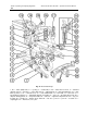
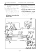
Proceed with Draft Control Sensor Ad-
justment, as follows:
а) set arm 1 (see Fig. 28) in the midpo-
sition;
b) remove the compression link (10) of
the hitch linkage mechanism, insert
compression link pin (11) into the top
hole of bracket-shackle (9);
c) by means of auxiliary lever (8) turn
the shackle on pin (13) in the direc-
tion of arrow "А", until spring (15) is
fully compressed. With the lever re-
leased, the shackle should regain its
initial position. In this case, the sen-
sor travel distance, measured as the
displacement of draft rod (5) should
be at least 11 mm;
г) made certain that the sensor is op-
erative, uncotter crown nut (12),
draw it up to the point of sensor
spring compression commencement.
then, turn it down additional 1/2 - 1/3
turn, to register slots in the nut with
the coyer-pin hole, and cotter the
nut.
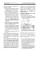
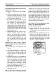
Following the draft sensor redjust-
ment, proceed with the adjustment of
draft tie-rod:
а) set the arm (1) in its midposition (see
Fig. 28);
b) using an additional lever (tube) for
the purpose, establish a force that
ensures the turn of the shackle to its
extreme position (in the direction of
arrow «А»);
c) retaining the lever in the forced out
position (along arrow стрелке «А»),
check for possible inserting of the
arm (1) prong into the slot in the
draft lever (3). If otherwise, adjust
the length of the tie-rod (5), so that
the arm (1) prong can enter freely in-
to the slot of the draft lever (3);
d) shorten the rod (5) by 1 turn of the
adjusting nuts (6).
With an agricultural implement attached
to the tractor, there is no need to use an
additional lever to adjust the draft tie-rod.
In this case it is enough to raise the im-
plement over the ground the tractor is on;
then, the weight of the implement will im-
pose sufficient tension on the draft sen-
sor through the central link. Keep in mind
that while doing so, the central link
should be in the upper hole of the rear
hitch leverage shackle. Raise the imple-
ment just to be off the ground.
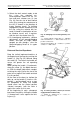
6.8.8. Hints of Tractor Operation with
Rear P.T.O.-Driven Implements
General Recommendations:
а) before connecting the machine to the
tractor, check to see that the rear
P.T.O. control is correctly adjusted (re-
fer to 7.6.7);
b) install and lock a required P.T.O. tail-
piece (8- or 24-spline) tail-piece and
lock reliably the required tail-piece, set
a corresponding speed drive; set 540
rpm for a 8-spline tail-piece, and 1000
rpm for a 21-spline tail-piece
Fig. 29