
Service manual


Belarus МТЗ-80.1/82.1/82Р — Руководство по эксплу-
атации и регулировки
Раздел 6. Правила эксплуатации и регулировки МТЗ-
80.1/82.1/82Р — Руководство по эксплуатации
66
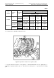
To replace the P.T.O. tail-piece, proceed
as follows: undo two bolts, remove the
hood and plate; turn out six bolts which
fasten holding plate (1) and take out the
tail-piece (2). Install another tail-piece
into the splined hole, and fix it with the
holding plate (1); tighten the six bolts,
place back the plate and the jacket, fas-
ten them with nuts.
Engage the P.T.O. independent drive at
diesel-engine minimum r.p.m. or with the
diesel-engine stopped.
Engagement of the synchronized P.T.O.
drive is to be performed on a running
diesel-engine, through smooth applica-
tion of the clutch.
Operating the tractor with the P.T.O. dis-
engaged, be sure to place the P.T.O.
control lever to the «P.T.O. Diseng
ed
»
position, set the P.T.O. two-speed drive
changeover clutch to position 1 (540
r.p.m.), and the independent-to-
synchronous P.T.O. drive changeover
lever — into its midpostion (neutral);
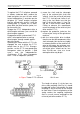
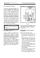
c) smear the shaft and the telescopic
joint of the universal-joint shaft with
solid oil. Install the universal joint onto
the P.T.O. shaft tail-end, fasten it reli-
ably in the slot. Make sure that the
lugs (2) of the joint yokes (1) (see Fig.
30) are in one and the same plane.
Failing to observe this requirement
causes overloads of the universal-joint
drive and the P.T.O.;
d) replace the protective jacket on the
universe-joint shaftу of the agricultural
machine;
e) with the universal-joint drive installed,
check to see that the components of the
shaft telescopic joint do not rest rigidly
in extreme positions of the machine rel-
ative to the tractor; the minimum over-
lap of the telescopic portion of the uni-
versal-joint drive should not be less
than 110-120 mm, since at a lesser
overlap the drive may disjoin.
Fig. 30
In Figure: Tractor P.T.O. tail-end 110-12- mm
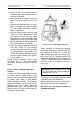
Fig. 31
The length of spring (1) of the farm ma-
chine safety coupling (see Fig. 31) should
be adjusted so that, at overloads, the claw
couplings 2 and 3 are free to turn relative
to each other. Excessive tightening of the
spring renders the coupling inoperative
and, as a result, causes overloads on the
universal-joint drive and the P.T.O.;