Air parking heater Technical description, installation, operation and maintenance instructions. Product type Order No. Diesel 2.2KW 12V 4A2002 12C14 Diesel 2.2KW 24V 4A2002 24C14 Diesel 4KW 12V 4A2004 12C14 Diesel 4KW 24V 4A2004 24C14 Air heater for operating independently of the engine.
Preface Thank you for choosing air parking heater. This instruction book describes the structures, working principles, installation and operation of the parking heater. For correct use of the heater, please read this instruction book carefully before installation and use. The instruction book shall be saved in a convenient place for later reference. Attention: ● This instruction book is subject to revision without notice, but the instruction book is in conformity to the purchased product.
1. Introduction Application scope This air heater is not affected by the engine, for in compliance with its heating power under the premise of installation in the following vehicles: ●Various properties of the car (at most 9 people) and its trailer. ●Agriculture working machinery. ●Boats、steamer and yacht(Limited to diesel heaters). ●Motor homes. Heater purpose ●Preheating and defrosting the glass. ●Heating and keeping the following warm: -Driver and working cabs. -Freight compartments.
-The heater air supply must consist of fresh air or circulated air and be sucked in from a clean area not contaminated by exhaust fumes of the drive machine, the combustion heater or any other source in the vehicle. -The intake pipe must be protected by a grid or other suitable means. ●Hot air outlet -The hot air pipes within the vehicle must be arranged or protected in such a way that there is no risk of injury or damage if they are touched.
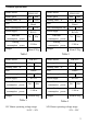
Technical specification Heater Model FJH-2.2/1C Heater Model FJH-2.2/2C Heater grade Min Max Heater grade Min Max Heating value(w) 850 2200 Heating value(w) 850 2200 Fuel Diesel Fuel consumption(l/h) 0.1 Power supply 0.28 DC12V Run time consumption power Starting consumption power Weight 7w 20w ≤100 w About 2.7Kg Fuel Fuel consumption(l/h) Power supply 0.1 0.28 DC24V Run time consumption power Starting consumption power Weight 7w 20w ≤100 w About 2.
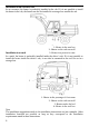
FJH-2.2/□C Main dimensions FJH-4/□□Main dimensions Fig.2 Fig.3 A=Exhaust 1- Minimum installation clearance (space) for opening the lid B=Fuel and for dismantling the glow plug and the controller. 2- Minimum installation clearance (space) for intake of heater air. C=Combustion air 3. Installation Installation and location The heater is suitable and certified for installation in parts of vehicles used by persons.
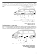
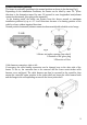
In a motor home, the heater is preferably installed in the inner compartment or luggage compartment. If it is not possible to install the heater in the passenger compartment or boot, the heater can also be mounted and protected against splashing water under the vehicle floor. Fig.
Installation in an excavator cab In an excavator, the heater is preferably installed in the cab. If it is not possible to install the heater in the cab, the heater can also be installed in a storage box outside the cab. Fig.6 1- Heater in the seat box 2- Heater on the cab rear wall 3- Heater in a protective case Installation in a truck In a truck, the heater is preferably installed inside the driver’s cab.
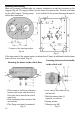
Possible installation positions The heater is preferably installing in the normal position as shown in the drawing Fig.8 Depending on the installation conditions, the heater can be titled by max. 30。(Flow ° direction to the bottom)or turned by max.
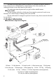
Mounting and fastening Make the necessary breakthroughs for exhaust, combustion air and fuel as shown in the diagram (Fig.10). The support surface for the heater foot must be flat. The hole φ10.5mm for the cable harness“dosing pump” is not included in the picture drawing and must be drilled after installation. Contour of the bearing surface Fig.10 Fig.11 If the sheet metal of the support surface is thinner than 1.5mm, an additional reinforcement plate will have to be fitted. (Fig.
Heater air system Risk of burning and injuries! ●The hose of the heater air system and the hot air outlet are to be routed and fastening in such a way that they pose no temperature risk to people、Animals or materials sensitive to temperature from radiation/contact or blowing directly. If necessary, a cover is to be fitted to the heater air system or hot air outlet. ●The outflow hood must be fitted on the hot air outflow side.
The optional air duct fittings Users can choose the air duct fittings according to the situation. Please refer to Fig.13. Warm air outlet No A B C D E F G Table 5 Specification φ90 Grill φ60 φ90/60 Diameter changes joint φ56/60 。 Elbow φ60/90 Clamp φ50~70 Ducting φ60/φ64 Connector φ60-φ60 Reducing T φ60 Name Fig. 15 Exhaust system The flexible exhaust pipe can be shortened to 20cm or lengthened to max.2m depending on the installation conditions.
●Exhaust pipes must be fastened safely(recommended clearance of 50cm)to avoid damage from vibrations. ●Route the exhaust system so that the emitted fumes are not sucked in with the combustion air. ●The mouth of the exhaust pipe must not get clogged by dirt and snow. ●The mouth of the exhaust pipe must not point in the direction of travel. Risk of injures and burns! Every type of combustion produces high temperatures and toxic exhaust fumes.
Fuel supply The following safety instructions must be observed when mounting the dosing pump, routing the fuel pipes and mounting the fuel tank. Deviations from the instructions stated here are not allowed. Failure to company can result in malfunctions. Danger! Risk of fire, explosion, poisoning and injuries! Switch off the vehicle engine and heater before refueling and before working on the fuel supply. ●No naked lights when handling fuel. ●Do not smoke. ●Do not inhale fuel vapors.
Installation position of the T-piece Use the installation positions shown in the diagram 18 when inserting a T-pipe 1-Direction of flow from the fuel tank 2-Direction of flow to the vehicle engine Fig.18 Fuel supply Fuel suction pipe install in the vehicle tank or independent fuel tank(optional) A Fig.
Installation position of the fuel pump Always mount the dosing pump with the pressure side rising upwards. Every installation ° ° ° position over 15 is allowed, although an installation position between 15 and 35 is preferable. Fig.20 ° ° 1-Installation position between 0 and 15 is not allowed. 。 。 2-Preferred installation position in range 15 and 35 ° ° 3-Installation position in range 35 and 90 is allowed. Damper installation Damper installation should be according to the practical situation.
Note After refueling with winter or cold diesel, the fuel pipes and the metering pump must be filled with the new by letting the heater run for 15 min. Possible suction and pressure height of the dosing pump Pressure height from vehicle tank to dosing pump: a=max.3000mm Intake height in pressure-less vehicle tank: b=max.1000mm for diesel b=max.500mm for petrol Intake height in vehicle tanks with withdrawal by negative pressure (valve with 0.03bar in tank cap) b=max.
4. Electrical system Heater wiring Note Safety instructions for wiring the heater The heater is to be connected up electrically according to the EMC directives. EMC can be affected if the heater is not connected up correctly. For this reason comply with the following instructions: Ensure that the insulation of electrical cables is not damaged. Avoid: chafing, kinking, jamming or exposure to heat.
Fig.
5. Operation and working condition ● Control Switches The control switch is shown in Fig. 25. It is used for the following operations: turning on or off of the heater; regulate the heating temperature or the heater power; eliminating locking of the heater due to trouble interrupt; converting working mode through the mode conversion button; Fig.
power)indication light turns yellow, use the control knob adjust heater power.(adjustable continuously). Press the ventilation button to turn the heater to the constant power oxygenation mode. Air conditioner (constant temperature) mode Press Air conditioner(constant temperature) mode button then Air conditioner(constant temperature) indication light turns red, use the control knob to set the control temperature of the heated area(adjustable continuously from 5℃to 35℃).
The fan runs on for approx.3 minutes to cool down then restart again. Switching off Press the button which the corresponding indicator light is on. Indicator light extinguished and fuel pump stop working after switching off the heater. The fan running and cooling down continuously about 3 minutes in the switch off process. Control and safety devices If the heater does not ignite within 90 seconds after starting the fuel pump, the start is repeated.
troubles may lead to locking state. In such case, you can press the button which is lighting on then work indicator goes out. Turn off the heater and keep it in such state for at least 5 seconds. Then restart the heater. When the following troubles occur, users can take measures to solve: Failure to turn on the heater and the indicator light is not illuminating; the reason is open circuit of fuse or wrong connection of wires.
function alone: In the Ventilation mode(fan rotation), press and hold the ventilation key does not release, first press the key on air conditioning, air conditioning light is lit, and then click the warm key, warm light is lit, all three lights lit,loosen the ventilation key, the oil pump began to pump oil (4Hz), three lights flashing at the same time, press any key to stop the pump oil. Three minutes after the automatic stop pump oil.
control switch anticlockwise to position “0 If electric welding is performed to the vehicle, please detach the positive wire of power supply of the heater from the battery and connect it to earth to protect the controller from any damage 8. Packing list Packing list No. Name Specification QTY FJH-2.2/1C ( ) 1 FJH-2.2/2C ( ) Parking heater FJH-4.0/1C ( ) Order No. 4A200212C14 1 FJH-4.
17 Exhaust pipe fixing clip φ27×16 t=0.8 2 29010002300 18 Gasket φ6/φ18 4 12010006500 19 Nut M6 4 12050003400 20 Self-drilling tapping screw ST5.5×30 5 12050003000 21 Cable ties 4×200 10 21990000000 22 Clip 23 Grill 24 Fuel suction pipe XYG-Ⅱ φ5*600 1 31000000500 25 Reducing T 10-6-10 1 12020015700 26 Reducing T 12-6-12 1 12020015800 27 Fuel pipe clip φ12/φ14 2 12010004600 28 Control switch KG-Ⅱ 1 31010700400 29 Protective gasket 47.