
Operating Guide


9
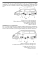
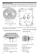
1-Heater air intake opening (fan wheel)
2-Position of the glow plug
3-Direction of flow
Fig.9
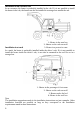
Possible installation positions
The heater is preferably installing in the normal position as shown in the drawing Fig.8
Depending on the installation conditions, the heater can be titled by max. 30。(Flow
direction to the bottom)or turned by max. 90
°
around its own longitudinal axis(exhaust
connection horizontal, glow plug points upwards!)
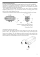
In the heating mode, the heater can deviate from the shown normal or maximum
installation positions by up to +15
°
in all directions because of a slanting position of the
vehicle or boat, without impaired functions.
Normal position horizontal (exhaust connection downwards)with tolerable swivel range
Cable harness connection, right or left
If necessary, the cable harness connection can be changed over to the other side of the
heater. To do so, the controller has to be removed and the lower semi-circular cable
harness cover unclipped. The cable harness can then be rerouted in the controller, then
mount the controller again, position in the jacket shell and insert the cable harness bush
and the bungs in the corresponding recesses in the lower jacket shell.
Fig.8