Technical Documentation Multi-Function Technology (MFT) for Damper and Control Valve Applications Effective May 2010
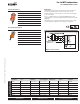
Multi-Function Technology® Your swiss army knife for HVAC. We set standards. www.belimo.com Features and benefits only Belimo's MFT can provide. Multi-Function Technology, only from solutions for individual applications, using the same programmable actuator. Whether you need a particular control or feedback signal, or need to change running speeds, MFT is the answer.
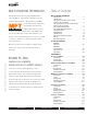
MULTI-FUNCTION TECHNOLOGY Table of Contents Belimo damper actuators and control valves with Multi-Function MULTI-FUNCTION TECHNOLOGY Nomenclature . . . . . . . . . . . . . . . . . . . . . . . . . . . . . . . 2 MFT Overview. . . . . . . . . . . . . . . . . . . . . . . . . . . . . . . 3 Spring Return Actuator Product Range Multi-Function Technology . . . . . . . . . . . . . . . . . . . . . 4 Non-Spring Return Actuator Product Range Multi-Function Technology . . . . . . . . . . . . . . . . . . . . .
Multi-Function Technology® Nomeclature 50 AR X 24 -MFT -S = Built-in Auxiliary Switch Valve B2 = 2-Way B3 = 3-Way B6 = 2-Way Flanged Control Power Supply -MFT = Multi- Valve Size 07-80 = 1/2”- 3” Torque Rating Version X* = Customized Non-Spring Return Cable GM = 360 in-lb 10 ft (3m) AM = 180 in-lb 16 ft (5m) NM = 90 in-lb Run Time LM = 45 in-lb Variable LU = 27 in-lb AH = 220 lbf LH = 100 lbf New Generation Spring Return AF = 180 in-lb NF = 90 in-lb Original Spring Return AF = 133 in-lb NF = 60
Multi-Function Technology® Control Parameter Variables Description VDC • Start: 0.5 to 30 VDC • Stop: 2.5 to 32 VDC (Minimum 2 VDC between start and stop required) P-100…(A…) configuration types are used for VDC control applications. Pre-set configurations are listed which offer solutions for standard control applications.
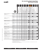
Spring Return Actuator Product Range Multi-Function Technology VDC Variable, Start 0 to 8, Span 2 to 10 VDC ● ● ● ● AFX24-MFT-S† ● 70…220 (150) <20♦ ● 10 7.5 (3.0) ● ● ● ● ● ● ● AFX24-MFT95† 70…220 (150) <20♦ ● 10 7.5 (3.0) ● ● ● AF24-MFT US† 75…300 (150) <20 ● 10 6.0 (2.5) ● ● ● ● ● ● ● AF24-MFT-S US† 75…300 (150) <20 ● 10 6.0 (2.5) ● ● ● ● ● ● ● AF24-MFT95 US† 75…300 (150) <20 ● 10 6.0 (2.5) ● ● ● Spring Return 2 SPDT, 7 A (2.
Control Input Floating Point Start and Span adj., Start 0.5 to 30 VDC, Span 2.5 to 32 VDC PWM adj., 0.02 to 50.0 Seconds 2-10 VDC (Default) VDC Variable, Start 0 to 8, Span 2 to 10 VDC Add-on ● ● ● ● ● 4.0 (1.5) ● GMX24-MFT95† ● 100-300 (150) ● 7 4.0 (1.5) AMX24-MFT ● 90-300 (150) ● 6 3.5 (1.3) ● ● ● ● AMCX24-MFT ● 35-120 (35) ● 6 3.5 (1.3) ● ● ● ● AMX24-MFT95 ● 90-150 (150) ● 6 3.5 (1.3) AMQX24-MFT ● ● 18 12 (1.
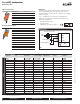
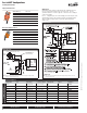
Pre-Set MFT Configurations DC Voltage Control Spring Return Actuators Application AFX24-MFT(-S) 180 in-lb AF24-MFT(-S) US 133 in-lb NFX24-MFT(-S) 90 in-lb NF24-MFT US 60 in-lb LF24-MFT(-S) US 35 in-lb LF24-MFT(-S)-20 US 35 in-lb TF24-MFT US 18 in-lb How the MFT actuator performs is determined by the configuration (P-10001, A01). The old generation actuators used a P-code (P-10001). The new generation actuators use a shorter 3 digit code. This shorter code is displayed on the reorder number.
Pre-Set MFT Configurations Pulse Width Modulation Control Spring Return Actuators Application AFX24-MFT(-S) 180 in-lb AF24-MFT(-S) US 133 in-lb NFX24-MFT(-S) 90 in-lb NF24-MFT US 60 in-lb LF24-MFT(-S) US 35 in-lb LF24-MFT(-S)-20 US 35 in-lb TF24-MFT US 18 in-lb How the MFT actuator performs is determined by the configuration (P-10001, A01). The old generation actuators used a P-code (P-10001). The new generation actuators use a shorter 3 digit code.
Pre-Set MFT Configurations Floating Point Control Spring Return Actuators Application AFX24-MFT(-S) 180 in-lb AF24-MFT(-S) US 133 in-lb NFX24-MFT(-S) 90 in-lb NF24-MFT US 60 in-lb 35 in-lb LF24-MFT(-S)-20 US 35 in-lb TF24-MFT US 18 in-lb P-3000… configuration types are used for floating point control outputs. In this application MFT actuators offer constant running time and standard feedback options. A IN4004 or IN4007 diode is required for original spring return actuators only.
Pre-Set MFT Configurations On/Off Control, P-4000… (J…) Spring Return Actuators Application 180 in-lb AF24-MFT(-S) US 133 in-lb NFX24-MFT(-S) 90 in-lb NF24-MFT US 60 in-lb LF24-MFT(-S) US 35 in-lb TF24-MFT US 18 in-lb In addition the MFT actuator offers additional functionality in the on/off mode, such as configuration P-40003 with minimum position and 2 to 10 VDC feedback. Wiring Diagram Non-Spring Return Actuators M40035 - 05/10 - Subject to change. © Belimo Aircontrols (USA), Inc.
Multi-Function Technology® Operation All MFT actuators have built-in brushless DC motors which provide better accuracy and longer service life. Control Accuracy and Stability (AF / NF / LF / TF) Control Accuracy and Stability (GM / AM / NM / LM / AH / LH / LU / GR / AR / LR) The …MFT US actuators are designed with a unique non-symmetrical deadband. The actuator follows an increasing or decreasing control signal with a 80 mV resolution.
Multi-Function Technology® Operation All Belimo actuators have built-in brushless DC motors which provide better accuracy and longer service life. Control Accuracy and Stability (AMQ / NMQ / LMQ / AHQ / LHQ) Belimo Quick Running non-spring return actuators are designed with a unique non-symmetrical deadband. The actuator follows an increasing or decreasing control signal with a 40 mV resolution.
Multi-Function Technology® Operation Running Time Motion Parameter Variables Description New Generation AF 70 to 220 seconds New Generation NF 40 to 220 seconds AF / NF / LF / TF 75 to 300 seconds GM 75 to 300 seconds Running time is selectable allowing for customizing the actuator for the application at hand. Adjustable running time allows for: • Matching HVAC system sequence of operation. • Improving control loop stability. • Reducing actuating noise (slower running).
Multi-Function Technology® Operation Motion Parameter Variables Description Adaptation OFF When the manual override button is depressed, and released, the actuator will perform synchronization. The actuator will simply drive to the mechanical zero position and return to its last control position. ON – Manual The default setting for adaptation is “ON – Manual”. When the ON-Manual setting is selected, adaptation is initiated by: •Pressing the manual override button once (GM / AM / NM / LM).
Multi-Function Technology® Specifications/Descriptions Specifications Parameter Variables Description Alarms - Fault A fixed voltage of 8.5 VDC is present when Alarm ‘sounds’. Hunting Alarm criteria: Actuator is hunting due to unstable control loop. This fault occurs when the ratio of Active time to Operating time exceeds 20%. Operating time: Total number of hours connected to power supply Active time: Total number of hours the actuator is in mechanical motion.
Multi-Function Technology® Specifications/Definitions Parameter Variables Identification Serial Number Displays the actuators internal serial number. Actuator Type / Software Version Displays the actuator nomenclature (AFX24-MFT US) and MFT software version. Assembly Location Displays the where the actuator was assembled. Setpoint Displays the actual control input position as a percentage. As signal input changes you will see the setpoint percentage change accordingly.
Multi-Function Technology® Wiring WARNING The wiring technician must be trained and experienced with electronic circuits. Disconnect power supply before attempting any wiring connections or changes. Make all connections in accordance with wiring diagrams and follow all applicable local and national codes. Provide disconnect and overload protection as required. Use copper, twisted pair, conductors only. If using electrical conduit, the attachment to the actuator must be made with flexible conduit.
Multi-Function Technology® Wiring W048_08 ATTENTION Master-Slave is the correct method for wiring multiple Belimo MFT actuators to a single load. For example, you can have up to three AFX24-MFT on a single damper jackshaft or two GMX24-MFT on a large butterfly valve. The current Belimo solution is to mount multiple actuators onto the damper or valve. In the past this required the installer to wire the actuators in a “masterslave” arrangement. This was typical for the AF24-SR US actuator.
Multi-Function Technology® Wiring Diagrams Spring Return Actuator with MFT VDC / 4 to 20mA Two Position PWM Original AF, NF, LF, TF New Generation AF, NF Floating Point Override control to min, mid, max positions W425_08 VDC / 4 to 20mA Two Position Floating Point Override control to min, mid, max positions 800-543-9038 USA 18 M40035 - 05/10 - Subject to change. © Belimo Aircontrols (USA), Inc.
Multi-Function Technology® Wiring Diagrams 0 to 135 Ω Control (MFT95) Wiring multiple actuators to a Series 90 controller M40035 - 05/10 - Subject to change. © Belimo Aircontrols (USA), Inc. Override Low Limit Control Wiring multiple actuators to a Series 90 controller using a minimum position potentiometer High Limit Control Typical wiring diagrams for multiple actuators used with the W973, W7100 and T775 controllers.
Multi-Function Technology® MFT VDC Proportional Control Program Codes Programmable Code A01 A02 A03 A04 A05 A06 A07 A08 A09 A10 A11 A12 A13 A14 A15 A16 A17 A18 A19 A20 A21 A22 A23 A24 A25 A26 A27 A28 PICCV ONLY A29 A30 A31 A32 A33 A34 A35 A37 A38 A39 A40 A41 A42 A43 A44 A45 A46 A47 A48 A49 A51 A52 A53 A54 A55 A56 A57 A58 A59 A60 A61 A62 A63 A64 A65 Running Time 150s 150s 150s 150s 150s 150s 150s 150s 150s 150s 150s 150s 150s 100s 150s 150s 150s 150s 100s 150s 150s 150s 150s 150s 76s 150s 150s 100s 150s 15
Multi-Function Technology® M40035 - 05/10 - Subject to change. © Belimo Aircontrols (USA), Inc.
Multi-Function Technology® Programmable Code AC1 AC2 000 AC4 AC5 AC6 AC7 AC8 AC9 ACA ACX AD0 AD1 AD2 AD3 AD4 AD5 AD6 AD7 AD8 AD9 ADA PICCV ONLY ADC ADD ADE ADF ADG ADH ADJ ADK ADL ADM ADN ADP ADR ADS ADT ADU ADV ADW ADX AE0 AE1 AE2 AE3 Running Time 90s 150s 150s 150s 75s 450s 150s 35s 45s 90s 150s 100s 100s 90s 35s 150s 100s Control Range 2…10V 0.5…10V 2…10V 0.5…10V 2…10V 2…10V … 0.5…10V 0.5…10V 0.5…10V 2...10V 0.5...5V 5…10V 2…10V 2…10V 2…10V 2...
Multi-Function Technology® MFT VDC Proportional Control Program Codes Running Time Control Range Feedback Feedback Range Obsolete Code MP Bus Logo Adaption 120s 75s 300s 450s 0.5…10V 0.5…10V 0.5…10V 0.5…10V U5 U5 U5 U5 U5 0.5…10V U5 0.5…10V U5 0.5…10V U5 0.5…10V --------- NO NO NO NO manual manual manual manual M40035 - 05/10 - Subject to change. © Belimo Aircontrols (USA), Inc.
Multi-Function Technology® MFT 95 (Honeywell Series 90, 0-135Ω) Program Codes Running Time 150s 150s 150s 75s 100s Control Range 0…135 Ohm 0…135 Ohm 0…135 Ohm 0…135 Ohm 0…135 Ohm Feedback U5 U5 U5 U5 U5 Feedback Range U5 2…10V U5 0.5…10V U5 0.5…5V U5 2…10V U5 0.
Multi-Function Technology® M40035 - 05/10 - Subject to change. © Belimo Aircontrols (USA), Inc.
Multi-Function Technology® MFT Floating Point Program Codes Running Time 150s 150s 100s 100s 100s 150s 300s 75s 85s 150s 75s 120s 90s 150s 150s 90s 60s 45s 35s Control Range --------------------------------------- Feedback U5 U5 U5 U5 U5 U5 U5 U5 U5 U5 U5 U5 U5 U5 U5 U5 U5 U5 U5 Feedback Range U5 2…10V U5 0.5…10V U5 2…10V U5 0.5…5V U5 0.5…10V U5 0.5…5V U5 2…10V U5 2…10V U5 2…10V U5 0.5…6V U5 0.5…5V U5 0.5…10V U5 2…10V U5 0.5…4.
Multi-Function Technology® M40035 - 05/10 - Subject to change. © Belimo Aircontrols (USA), Inc.
Multi-Function Technology® MFT Quick Actuators Proportional Control Program Codes Running Time 2.5s 4s 7s 10s 15s 20s 2.5s 4s 7s 10s 15s 20s Control Range 2…10V 2…10V 2…10V 2…10V 2…10V 2…10V 0.5…10V 0.5…10V 0.5…10V 0.5…10V 0.5…10V 0.5…10V Feedback U5 U5 U5 U5 U5 U5 U5 U5 U5 U5 U5 U5 Feedback Range U5 2...10V U5 2...10V U5 2...10V U5 2...10V U5 2...10V U5 2...10V U5 0.5...10V U5 0.5...10V U5 0.5...10V U5 0.5...10V U5 0.5...10V U5 0.5...
Multi-Function Technology® MFT Special Control (Non-Spring Return Only) Program Codes Running Time 150s 35s 45s 90s Control Range Phasecut Phasecut Phasecut Phasecut Feedback U5 U5 U5 U5 Feedback Range U5 2…10V U5 2…10V U5 2…10V U5 2…10V 150s 4…20mA U5 45s 90s 4…20mA 4…20mA 75s 75s 4…20mA Phasecut Obsolete Code MP Bus Logo NO NO NO NO Adaption manual manual manual manual U5 2…10V NO manual U5 U5 U5 2…10V U5 2…10V NO NO manual manual U5 U5 U5 2…10V U5 2…10V NO NO manual manual M4003
Multi-Function Technology® Programmable Code N01 N02 N03 N04 N05 N06 N07 N08 N09 N10 N11 N12 N13 N14 N15 N16 N17 N18 N19 N1A N1C N1D N1E N1F N1G N1H N1J N1K N1L N1M N1N N1P N1R N1S N1T N1U N1V N1W N1X N20 N21 N22 N23 N24 N25 N26 N27 N28 N29 N30 N3A Running Time 150s 150s 150s 150s 150s 150s 150s 150s 150s 150s 150s 150s 150s 150s 150s 150s 150s 150s 100s 150s 75s 150s 100s 150s 150s 150s 150s 150s 150s 150s 76s 75s 75s 150s 150s 150s 150s 150s 150s 150s 150s 150s 150s 150s 150s 150s 75s 75s 150s 100s 100s
Multi-Function Technology® SY-MFT Programmable Code ACE ACF ACG ACH ACJ ACK ACL ACM ACN ACP ACR ACS W3E** Loss of Control Signal stop stop stop stop open open open open close close close close stop Input Signal 2…10V 0.5…10V 4…20mA 4…20mA 2…10V 0.5…10V 4…20mA 4…20mA 2…10V 0.5…10V 4…20mA 4…20mA 0.02-5.00 seconds PWM Feedback U5 U5 U5 U5 U5 U5 U5 U5 U5 U5 U5 U5 U5 Output Signal U5 2...10V U5 0.5...10V U5 4…20mA U5 2...10V U5 2...10V U5 0.5...10V U5 4…20mA U5 2...10V U5 2...10V U5 0.5...
M40035 - 05/10 - Subject to change. © Belimo Aircontrols (USA), Inc. Multi-Function Technology® This page intentionally left blank.
M40035 - 05/10 - Subject to change. © Belimo Aircontrols (USA), Inc.
M40035 - 05/10 - Subject to change. © Belimo Aircontrols (USA), Inc. PC-Tool Accessories This page intentionally left blank.
MFT-P US Belimo PC-Tool Application The Belimo PC-Tool software is a graphical user interface which allows the user to set, modify and read actuator characteristics. The Belimo PC-Tool is an MFT support tool which is a practical solution for Controls distributors and Installation contractors.
ZIP-USB-MP US For interfacing PC with…MFT US type actuators Application The ZIP-USB-MP is used with the Belimo PC-Tool software (MFT-P US) to interface all Multifunctional (…MFT US) type actuators via a USB port. Monitoring and parameterization of one MFT actuator is enabled. The ZIP-USB-MP can also be used to interface the MFT actuators functionality via the UK24LON. Connection and Operation Power Supply Power for the ZIP-USB-MP is supplied via the connected MFT actuator.
ZIP-RS232 US For Interfacing PC with…MFT US Type Actuators Application The ZIP-RS232 is used with the Belimo PC-Tool software (MFT-P US) to interface all Multifunctional (…MFT US) type actuators via an RS232 port. Monitoring and parameterization of one MFT actuator is enabled. The ZIP-RS232 can also be used to interface the MFT actuators functionality via the UK24LON.
MFT Cables For Interfacing PC with…MFT US Type Actuators Belimo PC-Tool D-Sub ZK1-GEN Rx/Tx Enable Power Cable for use with ZIP USB-MP or ZIP-RS232 to connect new generation nonspring return actuators via diagnostic/programming socket RS232 ZK1-GEN D-Sub ZK1-GEN Wiring D-Sub Rx/Tx Enable Power Belimo PC-Tool RS232 24V D-Sub Com Wht (1) Common ZK2-GEN Blu (2) Hot ZK2-GEN Grn (5) Output/PP Cable to connect ZIP-RS232 with spring and non-spring return actuators not equipped with diagnostic/p
PC-Tool User Manual M40035 - 05/10 - Subject to change. © Belimo Aircontrols (USA), Inc.
M40035 - 05/10 - Subject to change. © Belimo Aircontrols (USA), Inc. PC-Tools User Manual This page intentionally left blank.
PC-Tool User Manual Table of Contents 1 2 Basics .......................................................................................................... 1-1 1.1 Introduction ...........................................................................................................................1-1 1.2 General structure of the user software ...................................................................................1-2 Getting started with PC-Tool ..........................................
PC-Tool User Manual 3.7 Configuring an actuator....................................................................................................... 1-29 3.7.1 Saving a parameter file ......................................................................................... 1-30 3.7.2 Loading a parameter file ....................................................................................... 1-30 3.7.3 Copying parameters............................................................................
PC-Tool User Manual 1 Basics 1.1 Introduction The user manual describes the functions of the Belimo PC-Tool. The Belimo PC-Tool is a PCbased tool for parameterizing Belimo MFT via bus. M40035 - 05/10 - Subject to change. © Belimo Aircontrols (USA), Inc. This document is designed to present basic information. This booklet is based on PC-Tool 3.4. Later versions may contain more features.
PC-Tool User Manual 1.2 General structure of the user software A B D C E Menu bar [A] and toolbar [B] provide functions that affect the program as a whole. An explanatory text (tooltip) appears for each icon in the toolbar when you position the mouse pointer on it. The MP-Channels and actuators belonging to the project are displayed in the outline bar [C] in the form of a tree (as in the Explorer). The object to be worked on is marked here.
PC-Tool User Manual Missing or invalid entries are indicated by a flashing exclamation mark. If you move the mouse pointer to the exclamation mark, an explanatory text (tooltip) appears. Inactive commands are displayed in gray letters (or as gray icons) according to the Windows standard. M40035 - 05/10 - Subject to change. © Belimo Aircontrols (USA), Inc. Texts in boxes with a black font on a gray background cannot be changed.
PC-Tool User Manual 2 Getting started with PC-Tool 2.1 Connecting the computer with the actuators There are two ways to connect the computer (PC-Tool) to the actuators, via the ZIP-RS232 or by the ZIP-USB-MP US. If the ZIP-RS232 is going to be used, follow the wiring diagram that works best for your situation. M40035 - 05/10 - Subject to change. © Belimo Aircontrols (USA), Inc. ZIP-RS232 via direct connection to MFT actuator.
PC-Tool User Manual ZIP-RS232 via ZK3-GEN to Belimo actuator. M40035 - 05/10 - Subject to change. © Belimo Aircontrols (USA), Inc. ZIP-RS232 via ZK5-GEN to Belimo actuator.
PC-Tool User Manual ZIP-RS232 via direct connection to LON actuator. M40035 - 05/10 - Subject to change. © Belimo Aircontrols (USA), Inc.
PC-Tool User Manual If the ZIP-USB-MP is going to be used, follow the directions to load the ZIP-USB-MP software and driver. Please note the ZIP-USB-MP is paired with the computer, if you move the ZIP-USBMP the software and driver must be installed on the new computer. ZIP-USB-MP via ZK1-GEN to a Belimo actuator. M40035 - 05/10 - Subject to change. © Belimo Aircontrols (USA), Inc. ZIP-USB-MP via ZK1-GEN to a Belimo actuator.
PC-Tool User Manual M40035 - 05/10 - Subject to change. © Belimo Aircontrols (USA), Inc. ZIP-USB-MP via ZK1-GEN to a Belimo actuator.
PC-Tool User Manual 2.1.1 Driver Installation A driver must be installed on the PC in order to use the ZIP-USB-MP. This driver can be downloaded from the Belimo website (Download section). Once the driver has been installed, the ZIP-USBMP is logged in on the PC as a virtual COM port. Supported operating systems M40035 - 05/10 - Subject to change. © Belimo Aircontrols (USA), Inc. Windows Vista WindowsXP Windows 2000 Windows ME Windows 98 Windows 98 SE Preparation Download the zipped “Driver_ZIP-USP-MP.
PC-Tool User Manual Installing A) Connect the ZIP-USB-MP to the USB port on your computer. The computer reports that it has detected new hardware and opens the following screen automatically: Hardware Update Wizard. B) Click the radio button as shown in the next screenshot: Install from a list or specific location (Advanced).
PC-Tool User Manual E) Select the XP_2000_ZipUsbMP_Driver folder and then click “OK”. F) Click “Next”. M40035 - 05/10 - Subject to change. © Belimo Aircontrols (USA), Inc. G) The driver is now installed. H) Click “Finish”.
PC-Tool User Manual I) After the driver has been installed, the USP port must be paired to a COM port. Click the radio button in the Wizard as shown in the next screenshot: Install from a list or specific location (Advanced). J) Click “Next”. M40035 - 05/10 - Subject to change. © Belimo Aircontrols (USA), Inc. K) The USB port is now paired to a COM port. L) Click “Finish”. NOTE: If a warning appears during the installation procedure, please ignore it and click “continue installation”.
PC-Tool User Manual 2.1.2 Checking Check the USB/COM connection on your computer. You must define a COM port number under “Options” in order to work with Belimo PC-Tool MFT-P v3. To find out which COM port number is the correct one, you need to check which COM port the USB port was automatically connected to by the system. A) Select “Settings/Control Panel/System” in the Windows “Start” menu. On the “Hardware” tab, click “Device Manager”. M40035 - 05/10 - Subject to change.
PC-Tool User Manual Selecting the same COM port in PC-Tool Version 3.4 M40035 - 05/10 - Subject to change. © Belimo Aircontrols (USA), Inc. After selecting the COM port, for example “COM=8” (a different COM number may apply on your PC), you can set to work with the Tool.
PC-Tool User Manual 2.2 Starting the program Click the program icon on your desktop. A start screen appears. Click the Start button (bottom right). 2.3 Adapting PC-Tool options M40035 - 05/10 - Subject to change. © Belimo Aircontrols (USA), Inc. When you start the program for the first time, a dialog is displayed for adapting the userspecific settings. PC-Tool options Select the desired language in the combobox here. If you change the language, exit the program and restart it.
PC-Tool User Manual 2.4 Creating a new project To work with the program, you have to create a "project". The dialog for entering the project data is displayed. Click the radio button "New project". The project name, company and user ID must be filled in; all other information is optional. 2.5 Setting up the program The project and the MP-Channel can be seen in the outline bar [C]. The bus is scanned every 10 seconds by default.
PC-Tool User Manual 2.6 Displaying actuator parameters Select the desired actuator in the outline bar [C] by clicking it with the mouse. The current settings for the actuator are displayed in the detail area [D]. M40035 - 05/10 - Subject to change. © Belimo Aircontrols (USA), Inc. Example of detail area [D] (damper actuator) 2.
PC-Tool User Manual 3 Basic functions 3.1 Program start After the program is started, a start screen is displayed. Click Start. Determine the project with which you would like to work. You can either open one of the last projects listed, open an existing project from a file, or create a new project. The defined MP-Channel is displayed and opened. A bus scan is started for each MP-Channel. If only one actuator is connected, it is automatically selected and displayed.
PC-Tool User Manual 3.2 Projects 3.2.1 Project data All user-specific data of the program are administered in the framework of projects. Each project has a project directory in the file system. The project files are stored in sub-directories of the project directory. The storage place of the project files is described in the Appendix. 3.2.2 Creating a new project Select File `, New Project in the main menu. Enter the new project data in the dialog.
PC-Tool User Manual 3.2.5 Exporting a project Copy the entire project folder in the Explorer, for example onto a CD or thumbdrive. 3.2.6 Copying a project Copy the entire project folder to another location in the Explorer. Give the project folder a new name. Give the project file (.bptpj) the same name within the new project folder. 3.2.7 Deleting a project Delete the entire project folder in the Explorer. The project to be deleted must not be currently open in the program. 3.3 MP-Channel 3.3.
PC-Tool User Manual MP-Channel settings 3.3.2 Bus scan In the bus scan section of the "MP-Channel settings" dialog, you can enter the time interval for the periodic bus scan in seconds. Permitted values are whole numbers between 1 and 9999. The program can address actuators in two basic ways: In multi-point mode (MP), up to 8 actuators of the types MP / MFT can be individually digitally addressed. M40035 - 05/10 - Subject to change. © Belimo Aircontrols (USA), Inc.
PC-Tool User Manual Option You can also select MP-Channel ` Trigger Scan in the main menu or activate the Trigger scan function by clicking the MP-Channel with the right mouse button. If more than one actuator responds at the same MP address during a bus scan or if more than one actuator is connected in PP mode, a bus jam will occur. This situation is indicated by the program with a corresponding message.
PC-Tool User Manual NOTE: USE THIS SECTION ONLY IF THE ACTUATORS (S) MP ENABLED. 3.4.1 Series addressing of actuators Click the Address device icon in the toolbar [B]. Option Click the MP-Channel with the right mouse button and select Addressing Device. Or select MPChannel ` Addressing Device in the main menu. M40035 - 05/10 - Subject to change. © Belimo Aircontrols (USA), Inc.
PC-Tool User Manual 3.4.2 Addressing with known serial numbers Each MP/MFT actuator is delivered with a label containing its individual serial number. These serial numbers can be used to assign a PP or an MP1 ... MP8 address to the actuator. An additional, removable label with an identical serial number is supplied with the actuator. If the actuator is installed at a particular position in the system, this additional label can be affixed at the same position in the system diagram.
PC-Tool User Manual 3.4.4 Addressing a single actuator Select the actuator in the outline bar [C] and click the "Change MP Address" icon in the toolbar [B]. Setting a new address Option Click the actuator with the right mouse button and select "Change MP Address" ("MP-Adresse ändern"). Select the new address in the combobox. If the address is already assigned to another actuator, a message will be displayed: M40035 - 05/10 - Subject to change. © Belimo Aircontrols (USA), Inc.
PC-Tool User Manual 3.5 Selecting a module All actuators that are active and connected to an MP-Channel are displayed in the outline bar [C]. Select the desired actuator from this display.
PC-Tool User Manual 3.6 Actuator parameters 3.6.1 Displaying actuator parameters The parameters of an actuator are displayed on the Service tab in the detail area [D]. Example of the "Service" tab (damper actuator) The Test, Adaptation and Synchronization functions are described for each respective module. M40035 - 05/10 - Subject to change. © Belimo Aircontrols (USA), Inc. 3.6.2 Printing out actuator parameters The displayed actuator parameters can be printed out.
PC-Tool User Manual Following messages may appear: Message Description Mechanical travel increased Expected end stop value for top or bottom has been overrun. Mechanical overload Actuator did not reach set point because an obstacle has reduced the operating range Excessive utilisation Actuator moves to often compared with the total operating time (typical relation of active time to operating time is greater than 25%) M40035 - 05/10 - Subject to change. © Belimo Aircontrols (USA), Inc.
PC-Tool User Manual 3.7 Configuring an actuator To change the parameters of an actuator, go to the Configuration tab. M40035 - 05/10 - Subject to change. © Belimo Aircontrols (USA), Inc. Example of the "Configuration" tab (damper actuator) The lower area with the basic settings can be displayed with the "More..." button and hidden again with the "Less" button.
PC-Tool User Manual Save the changed values in the actuator with the "Set" button underneath the status image. You can read out the parameters currently saved in the actuator again with the "Read" button. Entries for values that you have not previously saved in the actuator will be lost as a result. 3.7.1 Saving a parameter file You can store the displayed parameters in a file (with the extension .bptpar) with "Store to file…" on the "Configuration" tab.
PC-Tool User Manual Parameter files with factory settings M40035 - 05/10 - Subject to change. © Belimo Aircontrols (USA), Inc. Open the file which matches the actuator type. The settings are loaded into the input screen for the configuration. Afterwards, store the parameters in the actuator with the "Set" button.
PC-Tool User Manual NOTE: USE THIS SECTION ONLY IF THE ACTUATORS (S) MP ENABLED. 3.8 Parameterizing limited lots You can parameterize several identical actuators with the function "Parameterize Limited Lots". The number depends on the power of the voltage supply. To parameterize limited lots, save the parameter set to be programmed in a file. With one parameter set, you can only program actuators from the same actuator family (e.g. MFT), i.e. the parameter set used must match the actuator family.
PC-Tool User Manual Dialog for parameterizing limited lots M40035 - 05/10 - Subject to change. © Belimo Aircontrols (USA), Inc. Select the file with the saved parameters in the dialog. Position the cursor in the first input box for the serial number. Then press the acknowledge button on the first actuator which should be parameterized. If the buttons are not accessible, directly enter the serial numbers as described below.
PC-Tool User Manual If the address MP1 is already assigned to an actuator, a message will be displayed: Message when the address MP1 is already assigned (limited lot) Click OK to initially release the address MP1. The actuator that used to be assigned to this address will be set to PP. Click Cancel to stop the parameterization at this point.
PC-Tool User Manual 3.9 Printing labels To identify actuators, you can write self-adhesive labels with the PC-Tool program. A special printer may be necessary, depending on the type of label. 3.9.1 Setting up a configuration file Labels are defined per project. To print labels, set place holders (number in brackets) in the configuration file for the information to be printed. The structure and storage location of the configuration files are described in the Appendix. 3.9.
PC-Tool User Manual Select a printer and a configuration file. Enter the number of identical labels that are to be printed for "Number of labels per actuator". When parameterizing limited lots, the total number of printed labels is equal to this value times the number of actuators. Enter the desired texts {41} – {44} that are to be printed, if necessary. A maximum of 50 characters are available per text box. In text with consecutive numbering, a number is entered instead of the place holder "#".
PC-Tool User Manual Adapting a transformation table Click the transformation table icon. M40035 - 05/10 - Subject to change. © Belimo Aircontrols (USA), Inc. Option Click the project in the outline bar [C] with the right mouse button and select Transformation table. Or select Project `Transformation table in the main menu. Dialog for editing transformation tables Select an available transformation table using the combobox.
PC-Tool User Manual When you change a transformation table in one project, the changes do not affect corresponding tables in other projects. However, you can return to the original project folder from all projects through the entry in the combobox and open the changed table. Setting up a new transformation table When the dialog for editing a transformation table is open, you can create a new table with the "New" icon.
PC-Tool User Manual 3.11 Displaying recorded trend data Click the symbol Trend display. M40035 - 05/10 - Subject to change. © Belimo Aircontrols (USA), Inc. Option Click the project in the outline bar [C] with the right mouse button and select "Trend Recall". Or select Project ` Trend Recall in the main menu. Trend recall Select a trend file with the combobox. Keep the CTRL key pressed and pull the diagram to the left or right with the mouse in order to display values for other times.
PC-Tool User Manual 3.12 PC-Tool options Select Tools`PC-Tool options... in the main menu. Click the project in the outline bar [C] with the right mouse button and select PC-Tool options... M40035 - 05/10 - Subject to change. © Belimo Aircontrols (USA), Inc. Option Dialog for basic settings (general) "Project base path" sets the default directory in the file system, in which the new project folder will be saved. You can override this information when creating new projects, however.
PC-Tool User Manual C:\Documents and Settings\\My Documents. You can open the folder "My Documents" with the "My Computer" icon. The language that you select in the combobox will be used the next time that you start the program. Under "Log file", you can define whether a separate log file should be created each month or each week. Mark the "Activate MP-Monitor" checkbox to monitor the communication with the actuators with the diagnostic tool.
M40035 - 05/10 - Subject to change. © Belimo Aircontrols (USA), Inc.
PC-Tool User Manual 4 Attachment 4.1 Storage locations of files 4.1.1 Project data The default project is stored as a "Default project" sub-directory in the installation directory of the program. The projects are user-specific and are stored as a sub-directory in the user profile. For an English-language version of Windows, this is C:\Documents and Settings\\My Documents\Belimo\PCTool This directory contains sub-directories with the project names. 4.1.
PC-Tool User Manual 4.2 Configuration files for printing labels 4.2.1 Storage location The filenames have the extension *.bptlb. They are saved in the "label definition" directory for each project. For an English-language version of Windows, this is C:\Documents and Settings\\My Documents\Belimo\PCTool\ \label definition 4.2.2 Format The configuration files for label printing are stored in XML format. You can edit these files with an editor program, for example "Notepad".
PC-Tool User Manual 4.2.3 Boxes You can adapt the values for the page layout (values in millimeters) for new label formats. PageSize Page size (height and width) PageBorder Border width (top and left) = distance from the top left corner of the first label to the page border LabelSize Size of an individual label LabelBorder Label border width (top and left) = distance of the lettering from the label border M40035 - 05/10 - Subject to change. © Belimo Aircontrols (USA), Inc.
{0} Company name (from project data) {1} Project name {10} Actuator type {11} OEM designation {12} Position {13} Serial number {14} MP address {20} Control type Y {21} Feedback signal U5 {22} Range of rotation min – mid – max {23} Running time {24} Direction of rotation (cw /ccw) {25} Bus fail position {26} Sensitivity {27} Synchronization at {28} Torque {29} Nominal range {30} Conductance {31} Vnom {32} Vmax {34} Vmin {36} Control fct.
PC-Tool User Manual 4.2.4 Example of a label The following example results in a label having the dimensions width x height = 50 mm x 20 mm. The example is intended for an endless label printer that prints labels of the size 50 mm x 20 mm. The company name, the project name, the actuator type, the type of control signal and the running time are printed on the label. This data yields the following configuration file and the subsequently displayed label:
PC-Tool User Manual 4.3 Troubleshooting and error messages 4.3.1 General Problem After the program starts, an MP-Channel is not opened but displayed with the MP-Channel icon. Solution The MP-Channel cannot be opened, for example because the selected serial interface is assigned to another application. Check whether a modem or a communication program is using this interface. Error message Description Start adaptation failed. Communication failure on the MP-Channel or faulty actuator.
M40035 - 05/10 - Subject to change. © Belimo Aircontrols (USA), Inc. PC-Tool User Manual Error message Description Default project directory '…' does not exist! Please reinstall the application. When a new project is created, configuration files and sub-directories are normally copied from the default project in the installation directory of PC-Tool. The default project has probably been accidentally deleted, moved or renamed. Command ... unknown by the device Conflict between actuator and program.
Error message Description Error starting testscript The test script is invalid. Label printing error (Note the detailed instructions with the message regarding the reason for the error.) Error loading transformation table (Note the detailed instructions with the message regarding the reason for the error.) Error while loading project file: … (Note the detailed instructions with the message regarding the reason for the error.
PC-Tool User Manual Error message Description Could not find the VRP-M Tool executable. Would you search for it now? Concerns VRP-M controller. The corresponding program could not be found at the location specified in the PC-Tool options. M40035 - 05/10 - Subject to change. © Belimo Aircontrols (USA), Inc. Configure the path in the options (menu Tools/PC-Tool options in VRPM). Could not find PC-Tool V2.1. Would you search for it now? Affects VAV actuators.
Error message Description Series number has a wrong format! You have made a typing error while manually entering the serial number. Check the notation of the serial number. Reset alarm messages failed Communication failure on the MP-Channel or faulty actuator. Synchronization failed Communication failure on the MP-Channel or faulty actuator. The test script cannot be started because some conditions are not complied. A certain minimum air flow or system pressure is necessary for the test.
PC-Tool User Manual 4.3.3 ISO 8859-1/ANSI character set M40035 - 05/10 - Subject to change. © Belimo Aircontrols (USA), Inc. Only characters from the ISO 8859-1/ANSI character set are permitted in the "Description" and "Position" box Pos 32 33 34 35 36 37 38 39 40 41 42 43 44 45 46 47 48 49 50 51 52 53 54 55 56 57 58 59 60 61 62 63 Char ! " # $ % & ' ( ) * + , .
PC-Tool User Manual 4.4 Typical wiring diagrams 4.4.
PC-Tool User Manual 4.4.2 Typical wiring diagrams Typical wiring diagram 1 USB RJ11 (6/4) Belimo PC-Tool 24V GND ZK1-GEN USB 2 1 Typical wiring diagram 2 ~ T _ RJ11 (6/4) USB + AC 24 V DC 24 V ZK2-GEN Belimo PC-Tool MP GND USB white/weiss = GND blue/blau = not connected/nicht angeschlossen green/grün = MP ...MFT(2) ...A-MF ...A-MP ...D2-MP 800-543-9038 USA 866-805-7089 CANADA ...LON ...ALON ...D2LON 1 2 5 ~ T M40035 - 05/10 - Subject to change. © Belimo Aircontrols (USA), Inc. ...
PC-Tool User Manual Typical wiring diagram 3 MP-Master DDC Controller UK...Gateway RJ11 (6/4) USB ZK2-GEN Belimo PC-Tool GND 24 V MP USB GND white/weiss = GND blue/blau = not connected/nicht angeschlossen green/grün = MP MP ....A-MP …D2-MP ...MFT(2) USB RJ11 (6/4) Belimo PC-Tool ZK6-GEN USB RJ11 (6/4) Optimizer COU24-A-MP 800-543-9038 USA 1-56 30 866-805-7089 CANADA 203-791-8396 LATIN AMERICA M40035 - 05/10 - Subject to change. © Belimo Aircontrols (USA), Inc.
PC-Tool User Manual Typical wiring diagram 5 UK24LON/EIB MFT-H MP-Monitoring Pos. „MO“ LonTalk a b Power 0V 24V n.c. MP-Com. 0V 24V Y U/MP USB Belimo PC-Tool 3 pol ~T USB ZKS-MP AC 24 V _ DC 24 V + ....A-MP …D2-MP ...MFT(2) M40035 - 05/10 - Subject to change. © Belimo Aircontrols (USA), Inc.
PC-Tool User Manual Typical wiring diagram 7 USB RJ11 (6/4) Belimo PC-Tool CR24.. USB °°° °°° ZK1-VAV Belimo PC-Tool AC 230 V D-Sub 1 2 T ~ _ + 3 T OFF ~ Actuator ON U PP 1 2 5 RS232 ZIP-RS232 D-Sub 5 .....MFT(2) U5 MP .....A-MF .....A-MP 800-543-9038 USA 1-58 866-805-7089 CANADA 203-791-8396 LATIN AMERICA M40035 - 05/10 - Subject to change. © Belimo Aircontrols (USA), Inc.
PC-Tool User Manual for Damper and Valve Actuators M40035 - 05/10 - Subject to change. © Belimo Aircontrols (USA), Inc.
PC-Tools User Manual M40035 - 05/10 - Subject to change. © Belimo Aircontrols (USA), Inc. for Damper and Valve Actuators This page intentionally left blank.
PC-Tool User Manual for Damper and Valve Actuators Table of Contents 1 Introduction ................................................................................................... 2-1 2 Service......................................................................................................... 2-2 2.1 Displaying settings ................................................................................................................2-2 2.2 Adaptation ...........................................
PC-Tools User Manual M40035 - 05/10 - Subject to change. © Belimo Aircontrols (USA), Inc. for Damper Actuators This page intentionally left blank.
PC-Tool User Manual for Damper and Valve Actuators 1 Introduction The "Air module" user manual describes the detail area [D] of the Air module. The documentation is divided according to the three index tabs "Service", "Configuration" and "Simulation". Air and Water Actuators are basically the same. The water actuator has a linkage that connects the actuator to the valve.
PC-Tool User Manual for Damper and Valve Actuators 2 Service NOTE: This will display after successfully communicating to the actuator. 2.1 Displaying settings Service tab for full-rotation damper actuators For linear actuators the stroke is displayed instead of the angle of rotation, and the torque instead of the positioning force. Service tab for linear actuators (excerpt) 800-543-9038 USA 2-2 866-805-7089 CANADA 203-791-8396 LATIN AMERICA M40035 - 05/10 - Subject to change.
PC-Tool User Manual for Damper and Valve Actuators M40035 - 05/10 - Subject to change. © Belimo Aircontrols (USA), Inc.
PC-Tool User Manual for Damper and Valve Actuators 2.2 Adaptation In the adaptation, the actuator determines the range 0% ... 100% by approaching the mechanical limits. Click the "Adaptation" button on the Service tab. Option You can also trigger the adaptation directly on the actuator. The necessary buttons for this can be programmed. For example, "Manual button [once]" can be assigned the adaptation function. The progress of the adaptation is displayed in the status line.
PC-Tool User Manual for Damper and Valve Actuators Function test The function test checks for opening and closing. First of all, the drive moves to the mechanical stop according to the synchronization position. If the angle of rotation (or stroke) is set to "adapted", movement takes place to the other stop; with "programmed", on the other hand, to the programmed range limit. M40035 - 05/10 - Subject to change. © Belimo Aircontrols (USA), Inc. Click the "Test" button on the Service tab.
PC-Tool User Manual for Damper and Valve Actuators If the test reports an invalid actuator configuration, go to the "Configuration" tab after ending the test. The values that are not allowed are marked with a flashing exclamation point. You can save the test report as a file by clicking the floppy disk icon, and you can print it with the printer icon. End the function test with the "Close Test" button. The program asks whether you want to save an unsaved test report now.
PC-Tool User Manual for Damper and Valve Actuators 3 Configuration M40035 - 05/10 - Subject to change. © Belimo Aircontrols (USA), Inc. On the "Configuration" tab, you can read out parameter values from the actuator, change them and save them back to the actuator. The valid ranges for the parameter values are displayed in parentheses next to the input boxes.
PC-Tool User Manual for Damper and Valve Actuators For linear actuators, the stroke is displayed instead of the angle of rotation and the stroke direction instead of the direction of rotation.
PC-Tool User Manual for Damper and Valve Actuators VAV 4 +/- 6 V When this function is selected, the actuator is parameterized as a VAV actuator and can therefore be controlled by the VAV controllers VR.. . Note: When VAV (6 ± 4 V) is selected, the values for minimum, maximum, intermediate value, running time and angle of rotation/stroke are reset to the default values. 4–20 mA (Direct current) Fixed operating range DC 4–20 mA Note: This selection is only available for certain drives (e.g.
PC-Tool User Manual for Damper and Valve Actuators An existing value for Mid is automatically adapted when Min and Max are entered: If you enter Min, Mid is always larger than or equal to this input value. If you enter Max on the other hand, Mid is always less than or equal to this value. Examples of settings for control signal Y / feedback U5 Control signal Y: Feedback U5 : 3...8 V min: 30%, max : 70% 2...
PC-Tool User Manual for Damper and Valve Actuators Angle of rotation (for full-rotation actuators) / Stroke (for linear actuators) Adapted from the mechanical limits of certain angle of rotation range/stroke Programmed Angle of rotation range (full-rotation) or stroke (linear), the valid values depend on the maximum nominal setting range of the actuator Direction of rotation (for full-rotation actuators) cw Damper opening in the clockwise direction ccw Damper opening in counterclockwise direction S
PC-Tool User Manual for Damper and Valve Actuators Synchronization at Y = 0% Moves to the mechanical limit at zero stop (depending on the direction of rotation / stroke direction) Y = 100% Moves to the mechanical limit at full angle of rotation (depending on direction of rotation / stroke direction) Note: When the nominal setting range is set to "programmed", then the synchronization MUST be carried out at Y=0%. Torque (for full-rotation actuators) / Positioning force (for linear actuators) 25% ...
PC-Tool User Manual for Damper and Valve Actuators Manual button [once]/[twice] Synchronization Moves to a mechanical limit (according to the setting "Synchronization at") when the manual button is pressed once or twice respectively Adaptation Moves to both mechanical limits and recalculates angle-dependent parameters when the manual button is pressed once or twice respectively For "New Generation" actuators (types MFT, MP), the function Manual button [twice] is not available.
PC-Tool User Manual for Damper and Valve Actuators 4 Controller simulation Simulation tab for damper actuators The controller simulation is not possible while the actuator is performing an adaptation or synchronization. 800-543-9038 USA 2-14 866-805-7089 CANADA 203-791-8396 LATIN AMERICA M40035 - 05/10 - Subject to change. © Belimo Aircontrols (USA), Inc. Go to the "Simulation" tab.
PC-Tool User Manual for Damper and Valve Actuators 4.1 Actuator control Select the type of setpoint definition with the radio buttons. Setpoint Y (only available in PP mode): Control signal at connection Y according to selected control type (DC, PWM, open/close, 3-point). Setpoint Tool (not available with control type open/close or 3-point): The setpoint is entered in % of the programmed range. 0% is the minimum, 100% the maximum.
PC-Tool User Manual for Damper and Valve Actuators On the Service tab, a section with the sensor values is displayed to the right of the actuator control. Sensor display in MP mode Select the type of the connected sensor with the radio buttons. The value is either displayed in volts (active), ohms (passive) or as on/off (switch). The transformation table allows you to additionally convert the raw value of the sensor into the corresponding measuring quantity (temperature etc.).
PC-Tool User Manual for Damper and Valve Actuators Trend plot M40035 - 05/10 - Subject to change. © Belimo Aircontrols (USA), Inc. The Comment button allows you to enter a text at a defined time and the text is then saved in the trend file. If you want to record a trend for more than one hour (long-term trend), enter a value of at least 2 seconds for the interval. If the interval is shorter, too many data points will result and the time for correcting the curve between the queries can become too short.
PC-Tool User Manual for Damper and Valve Actuators 5 PC-Tool options Select Tools ` Options in the main menu. Option Click the right mouse button on the program icon in the outline bar and select "Options". Select "Air module" on the left. Using the combobox "Default tab", you can select the index tab you want to open by default when starting the program PC-Tool. If you would like to show the function table in the Configuration register, activate the “Show function table“ checkbox.
PC-Tool User Manual for NV/NVF Series Actuators M40035 - 05/10 - Subject to change. © Belimo Aircontrols (USA), Inc.
M40035 - 05/10 - Subject to change. © Belimo Aircontrols (USA), Inc. PC-Tool User Manual This page intentionally left blank.
PC-Tool User Manual for NV/NVF Series Actuators Table of Contents 1 Introduction ................................................................................................... 3-3 2 Service......................................................................................................... 3-4 2.1 Displaying settings ................................................................................................................3-4 2.2 Adaptation ..............................................
PC-Tool User Manual M40035 - 05/10 - Subject to change. © Belimo Aircontrols (USA), Inc. for SY-MFT Series Actuators This page intentionally left blank.
PC-Tool User Manual for NV/NVF Series Actuators 1 Introduction M40035 - 05/10 - Subject to change. © Belimo Aircontrols (USA), Inc. The "Water module" user manual describes the detail area [D] of the Water module for globe valve actuators. The documentation is divided according to the three tabs "Service", "Configuration" and "Simulation".
PC-Tool User Manual for NV/NVF Series Actuators 2 Service 2.1 Displaying settings M40035 - 05/10 - Subject to change. © Belimo Aircontrols (USA), Inc. The Service tab gives an overview of the current settings of the actuator.
PC-Tool User Manual for NV/NVF Series Actuators M40035 - 05/10 - Subject to change. © Belimo Aircontrols (USA), Inc.
PC-Tool User Manual for NV/NVF Series Actuators Control element diagram with open linear actuator The progress of the adaptation is displayed in the status line. The actuator first moves against the programmed direction to the zero stop and then to the end stop at full stroke. M40035 - 05/10 - Subject to change. © Belimo Aircontrols (USA), Inc.
PC-Tool User Manual for NV/NVF Series Actuators 3 Configuration M40035 - 05/10 - Subject to change. © Belimo Aircontrols (USA), Inc. On the "Configuration" tab, you can read out parameter values from the actuator, change them and save them back to the actuator. The valid ranges for the parameter values are displayed in parentheses next to the input boxes.
PC-Tool User Manual for NV/NVF Series Actuators Control signal Y 3-point AC voltage, positions: Open / neutral / closed Open / closed DC or AC voltage, 2-point DC 0.5–10 V (DC voltage) fixed operating range DC 0.5–10 V DC 2–10 V modulating (DC voltage) fixed operating range DC 2–10 V DC variable Start (Y=0%) 0.5 ... 30 Volt Stop (Y=100%) 2.5 ... 32 Volt Range between start and stop at least 2 V PWM 0.02–5 s Duration of the control impulse (pulse width modulation), fixed operating range PWM 0.
PC-Tool User Manual for NV/NVF Series Actuators Examples of settings for control signal Y / feedback U5 Control signal Y: Feedback U5 : 3...8 V min: 30%, max : 70% 2...7 V start: 20%, stop: 90% Position Open 100% 50% Y/U5 [V] Close 0% 0 5 10 M40035 - 05/10 - Subject to change. © Belimo Aircontrols (USA), Inc.
PC-Tool User Manual for NV/NVF Series Actuators Closing point (in acc. with switch S3.2) top The linear spindle is moved into the actuator with the valve closed and the stem is moved out of the fitting. bottom The linear spindle is moved out of the actuator with the valve closed and the stem is moved into the fitting.
PC-Tool User Manual for NV/NVF Series Actuators 4 Controller simulation M40035 - 05/10 - Subject to change. © Belimo Aircontrols (USA), Inc. Go to the "Simulation" tab. "Simulation" tab for globe valve actuators The controller simulation is not possible while the actuator is performing an adaptation or synchronization. 4.1 Actuator control Select the type of setpoint definition with the radio buttons.
PC-Tool User Manual for NV/NVF Series Actuators The control is switched off when you click Motor stop. This function is not available with the control types open/close and 3-point. Measurement values During the simulation, the stroke is displayed in % of the absolute (mechanically limited) range in millimeters and – converted according to the scale setting – as a feedback voltage in volts. 4.
PC-Tool User Manual for NV/NVF Series Actuators Select the type of the connected sensor with the radio buttons. The value is either displayed in volts (active), ohms (passive) or as on/off (switch). The transformation table allows you to additionally convert the raw value of the sensor into the corresponding measuring quantity (temperature etc…). (See the "Transformation table" section in the General User Manual) 4.
PC-Tool User Manual for NV/NVF Series Actuators The Comment button allows you to enter a text at a defined time and the text is then saved in the trend file. M40035 - 05/10 - Subject to change. © Belimo Aircontrols (USA), Inc. If you want to record a trend for more than one hour (long-term trend), enter a value of at least 2 seconds for the interval. If the interval is shorter, too many data points will result and the time for correcting the curve between the queries can become too short.
PC-Tool User Manual for NV/NVF Series Actuators 5 PC-Tool options Select Tools`PC-Tool options... in the main menu. Variant Click the project in the outline bar [C] with the right mouse button and select PC-Tool options. M40035 - 05/10 - Subject to change. © Belimo Aircontrols (USA), Inc. Dialog for basic settings (Water module) Select "Water/globe module" on the left. Using the combobox "Default tab", you can select the index tab you want to open by default when starting the program PC-Tool.
PC-Tool User Manual M40035 - 05/10 - Subject to change. © Belimo Aircontrols (USA), Inc.
PC-Tool User Manual for ePIV Series Actuators PC-Tool V3.5 ePIV Module M40035 - 05/10 - Subject to change. © Belimo Aircontrols (USA), Inc.
PC-Tool User Manual M40035 - 05/10 - Subject to change. © Belimo Aircontrols (USA), Inc.
PC-Tool User Manual for ePIV Series Actuators Table of Contents Introduction ..................................................................................................................... 4-3 2 Service............................................................................................................................ 4-4 2.1 Show Settings ........................................................................................................ 4-4 2.2 Adaption ................................
PC-Tool User Manual M40035 - 05/10 - Subject to change. © Belimo Aircontrols (USA), Inc.
PC-Tool User Manual for ePIV Series Actuators 1 Introduction The ePIV Module User Manual describes the detail area [D] of the module for the ePIV controller (Electronic Pressure Independent Valve, pressure-independent flow controller). The documentation is divided up in accordance with the tabs for "Service", "Configuration" and "Simulation". M40035 - 05/10 - Subject to change. © Belimo Aircontrols (USA), Inc. Note For function and wiring, see Product Information.
PC-Tool User Manual for ePIV Series Actuators 2 Service 2.1 Show Settings Service tab for EPIV controller In the general section of this user manual, a description is given as to how you can print out the control parameters [chapter 3.6.2.] or delete the maintenance and error messages [chapter 3.6.3]. 800-543-9038 USA 4-4 866-805-7089 CANADA 203-791-8396 LATIN AMERICA M40035 - 05/10 - Subject to change. © Belimo Aircontrols (USA), Inc.
PC-Tool User Manual for ePIV Series Actuators Meaning of the settings Control function Flow control or open loop operation Control function Y Type of control. If the control function is interpreted as inverted, then this will be displayed. Characteristic curve The EPIV controller works with either an equal-percentage or a linear characteristic curve. Characteristic curve off means "linear", characteristic curve on means "equal percentage". M40035 - 05/10 - Subject to change.
PC-Tool User Manual for ePIV Series Actuators Converting units for volumetric flow Select Tools ` PC-Tool Options in the main menu. Click on "EPIV Module" at the left.
PC-Tool User Manual for ePIV Series Actuators 2.4 Function Test The opening and closing of the valve is checked during the function test. The actuator first moves in accordance with the synchronisation position to the mechanical end stop. If the range is set to "adapted", then the other end stop will be approached; if it is set to "programmed", on the other hand, then it will move to the programmed range limit. M40035 - 05/10 - Subject to change. © Belimo Aircontrols (USA), Inc.
PC-Tool User Manual for ePIV Series Actuators If the test reports an invalid controller configuration, switch over to the "Configuration" tab after the test has been completed. There you will find the non-permitted values marked with a flashing exclamation mark. You can save the test report as a file by clicking on the floppy disk symbol or print it out by pressing on the printer symbol. End the function test by pressing on the "Close Test" button.
PC-Tool User Manual for ePIV Series Actuators 3 Configuration M40035 - 05/10 - Subject to change. © Belimo Aircontrols (USA), Inc. In the "Configuration" tab, you can read out the parameter values from the EPIV controller, modify them and save them as a text file. "Configuration" tab for EPIV controller The extended configuration in the lower area will become visible when you click on "Expand".
PC-Tool User Manual for ePIV Series Actuators 3.1 Settings Controller ID1 Designation 16 characters of any text Position 16 characters of any text Valve size Selection list with valve Sets the valve size and thus also the nominal volumetric sizes flow specified by the manufacturer (default nominal volumetric flow, if a release code is available, can be modified. See below: "Display scaling").
PC-Tool User Manual for ePIV Series Actuators off Control function Y normal (highest voltage = V’max) Feedback U5 (active only if actuator address is set to PP) Volumetric flow 0.5 … 10V Volumetric flow feedback 0 … 100%, V'nom = 0.5 … 10V Volumetric flow 2 … 10V Volumetric flow feedback 0 … 100%, V'nom = 2 … 10V Volumetric flow variable Volumetric flow feedback 0 … 100%, V'nom Start 0.0 ... 8.0 volt / stop 2.0 ... 10.
PC-Tool User Manual for ePIV Series Actuators 4 Controller Simulation "Simulation" tab for VAV controllers Control simulation will be influenced if the actuator is currently carrying out an adaption or a synchronisation. The "Motor Stop" function overrides any ongoing adaption or synchronisation. 800-543-9038 USA 4-12 866-805-7089 CANADA 203-791-8396 LATIN AMERICA M40035 - 05/10 - Subject to change. © Belimo Aircontrols (USA), Inc. Switch over to the "Simulation" tab.
PC-Tool User Manual for ePIV Series Actuators 4.1 Actuator Control (Actuator) Use the radio buttons to select the setpoint specification. Setpoint Y: Control function at connection Y. Setpoint tool: Input of the setpoint in % of the volumetric flow (100% corresponds to V'max), as volumetric flow value (e.g. l/min) or as control function (volts). Clicking on "Motor Stop" stops the actuator. The following override steps can be specified per radio button.
PC-Tool User Manual for ePIV Series Actuators Name of the test file Functions Test_EPIV_Max 3m.bptts V'max – 3 minutes Test_EPIV_Max-Auto-Min 9m.bptts V'max – 3 minutes Auto – 3 minutes M40035 - 05/10 - Subject to change. © Belimo Aircontrols (USA), Inc.
PC-Tool User Manual for ePIV Series Actuators 4.3 Recording Trends The progression over time of the setpoint and actual values can be displayed in a diagram during the simulation. The values are saved to a trend file and can be displayed again at a later date. In addition, commentary texts of one's choosing can be added.
PC-Tool User Manual for ePIV Series Actuators 5 PC-Tool Options for EPIV Module Select Tools ` PC-Tool Options in the main menu. Right-hand mouse click on the program symbol in the overview bar and select PC-Tool Options. Dialogue for basic settings (EPIV Module) Click on "EPIV Module" at the left. Main window In accordance with the most frequent usage, use the "Default Register" Combobox to determine which tab is to be opened in the default settings when the program is started up.
PC-Tool User Manual for SY-MFT Series Actuators M40035 - 05/10 - Subject to change. © Belimo Aircontrols (USA), Inc.
PC-Tool User Manual for SY-MFT Series Actuators
PC-Tool User Manual for SY-MFT Series Actuators Table of Contents Introduction..................................................................................................................... 5-3 2 Service ........................................................................................................................... 5-4 2.1 Displaying settings ................................................................................................. 5-4 2.2 Adaptation...............................
PC-Tool User Manual M40035 - 05/10 - Subject to change. © Belimo Aircontrols (USA), Inc. for SY-MFT Series Actuators This page intentionally left blank.
PC-Tool User Manual for SY-MFT Series Actuators 1 Introduction This user manual describes the detail area for valves using SY actuators. The documentation is divided according to the three tabs "Service", "Configuration" and "Simulation". In April 2008, Belimo launched the new SY-MFT to replace its existing proportional actuator the SYx-P. The new electronics, designed by Belimo's engineering group, was an extension of the new generation non-spring actuator platform successfully launched years prior.
PC-Tool User Manual for SY-MFT Series Actuators 2 Service 2.1 Displaying settings M40035 - 05/10 - Subject to change. © Belimo Aircontrols (USA), Inc. The Service tab gives an overview of the current settings of the actuator.
PC-Tool User Manual for SY-MFT Series Actuators M40035 - 05/10 - Subject to change. © Belimo Aircontrols (USA), Inc.
PC-Tool User Manual for SY-MFT Series Actuators The progress of the adaptation is displayed in the status line. The actuator first moves against the programmed direction to the zero stop and then to the end stop at full stroke. M40035 - 05/10 - Subject to change. © Belimo Aircontrols (USA), Inc. Next, the absolute values for a programmatically limited angle of rotation range (minimum, mid-position, and maximum) as well as the feedback signal U5 are recalculated and displayed.
PC-Tool User Manual for SY-MFT Series Actuators 3 Configuration On the "Configuration" tab, you can read out parameter values from the actuator, change them and save them back to the actuator. The valid ranges for the parameter values are displayed in parentheses next to the input boxes. "Configuration" tab for SY-MFT actuators Control Signal Y: Selectable: Options M40035 - 05/10 - Subject to change. © Belimo Aircontrols (USA), Inc. Feedback U5: Selectable: Options 2-10vdc, 0.
PC-Tool User Manual for SY-MFT Series Actuators Control signal Y 3-point AC voltage, positions: Open / neutral / closed Open / closed DC or AC voltage, 2-point DC 0.5–10 V (DC voltage) fixed operating range DC 0.5–10 V DC 2–10 V modulating (DC voltage) fixed operating range DC 2–10 V DC variable Start (Y=0%) 0.5 ... 30 Volt Stop (Y=100%) 2.5 ... 32 Volt Range between start and stop at least 2 V PWM 0.02–5 s Duration of the control impulse (pulse width modulation), fixed operating range PWM 0.
PC-Tool User Manual for SY-MFT Series Actuators Examples of settings for control signal Y / feedback U5 Control signal Y: Feedback U5 : 3...8 V min: 30%, max : 70% 2...7 V start: 20%, stop: 90% Position Open 100% 50% Y/U5 [V] Close 0% 0 5 10 M40035 - 05/10 - Subject to change. © Belimo Aircontrols (USA), Inc.
PC-Tool User Manual for SY-MFT Series Actuators Closing point (in acc. with switch S3.2) top The linear spindle is moved into the actuator with the valve closed and the stem is moved out of the fitting. bottom The linear spindle is moved out of the actuator with the valve closed and the stem is moved into the fitting.
PC-Tool User Manual for SY-MFT Series Actuators 4 Controller simulation M40035 - 05/10 - Subject to change. © Belimo Aircontrols (USA), Inc. Go to the "Simulation" tab. "Simulation" tab for SY-MFT actuators The controller simulation is not possible while the actuator is performing an adaptation or synchronization. 4.1 Actuator control Select the type of setpoint definition with the radio buttons.
PC-Tool User Manual for SY-MFT Series Actuators The control is switched off when you click Motor stop. This function is not available with the control types open/close and 3-point. Measurement values M40035 - 05/10 - Subject to change. © Belimo Aircontrols (USA), Inc. During the simulation, the stroke is displayed in % of the absolute (mechanically limited) range in millimeters and – converted according to the scale setting – as a feedback voltage in volts.
PC-Tool User Manual for SY-MFT Series Actuators 4.2 Trend recording During simulation, the time progress of the setpoints and actual values can be displayed in a plot. The values are saved in a trend file and can be displayed again at a later time. Furthermore, you can add any comment texts you would like. In the PC-Tool options "General", you determine whether the trend file is automatically saved when the recording is finished (checkbox not selected) or whether the program should ask you.
PC-Tool User Manual for SY-MFT Series Actuators The Comment button allows you to enter a text at a defined time and the text is then saved in the trend file. M40035 - 05/10 - Subject to change. © Belimo Aircontrols (USA), Inc. If you want to record a trend for more than one hour (long-term trend), enter a value of at least 2 seconds for the interval. If the interval is shorter, too many data points will result and the time for correcting the curve between the queries can become too short.
PC-Tool User Manual for SY-MFT Series Actuators 5 PC-Tool options Select Tools`PC-Tool options... in the main menu. Variant Click the project in the outline bar [C] with the right mouse button and select PC-Tool options. M40035 - 05/10 - Subject to change. © Belimo Aircontrols (USA), Inc. Dialog for basic settings (Water module) Select "Air module" on the left. Using the combo box "Default tab", you can select the index tab you want to open by default when starting the program PC-Tool.
PC-Tool User Manual M40035 - 05/10 - Subject to change. © Belimo Aircontrols (USA), Inc. for SY-MFT Series Actuators This page intentionally left blank.
ACR Supply Company Inc. 2719 Hillsborough Road Durham, NC 27705 Phone: 919-286-2228 With branches in NC Aireco Supply 9120 Washington Boulevard Savage, MD 20763-0414 Phone: 301-953-8800 With branches in MD, VA Amcon Controls, Inc. 11906 Warfield Street San Antonio,TX 78216 Phone: 210-349-6161 With a branch in Houston, TX L30014 - 04/10 - Subject to change. © Belimo Aircontrols (USA), Inc.
L30014 - 04/10 - Subject to change. © Belimo Aircontrols (USA), Inc. Belimo worldwide: www.belimo.com BELIMO Americas USA Locations, 43 Old Ridgebury Road, Danbury, CT 06810 Tel. 800-543-9038, Fax 800-228-8283, marketing@us.belimo.com 1049 Fortunado Loop, Sparks, NV 89436 Tel. 800-987-9042, Fax 800-987-8875, marketing@us.belimo.com Canada Locations, 14/16 – 5716 Coopers Avenue, Mississauga, Ontario L4Z 2E8 Tel. 866-805-7089, Fax 905-712-3124, marketing@us.belimo.