
User's Manual


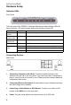
Table Of Contents
- Introduction
- Hardware Setup
- Indicator LEDs
- Connecting Devices
- 1. Connecting Computers with Wires: Connect computers directly to the Gateway on ports 1-4 on the...
- 2. Connecting Wireless Computers: Simply make sure your wireless computers are within range of th...
- 3. Connecting a Cable Modem or DSL Modem: Connect your Cable or DSL modem to the WAN port on the ...
- 4. Power: Plug the power adapter into the power jack (9 V/1000 mA).
- 5. Reset Button: The Reset Button is designed and positioned at rear panel for rebooting and rese...
- Configuring Wireless Connections
- Configuring Your Computer
- Configuring Your Computer with Windows 95/98/Me
- Step 1. Configure TCP/IP Settings
- 1. From the Windows desktop, click the “Start” button. Choose “Settings,” then click “Control Pan...
- 2. From “Control Panel” Double-click the “Network” icon.
- 3. In the “Network” window, under the “Configuration” tab, double-click the “TCP/ IP” component t...
- 4. Select the “IP Address” tab. If “Obtain an IP address automatically” is already selected, your...
- 5. Locate your IP address and Subnet Mask. Record them in the spaces below.
- 6. Click the “Gateway” tab and record the numbers listed under “Installed gateways.”
- 7. Click the “DNS Configuration” tab. Locate the DNS servers listed under “DNS Server Search Orde...
- 8. After writing down your settings, check to make sure you have recorded them correctly. Click t...
- 9. Windows may need your Windows 95/98/Me CD to copy some files. After it finishes copying, it wi...
- Step 2. Disable HTTP Proxy
- Internet Explorer
- 1. Open Internet Explorer and click the “Stop” button. Click “Tools,” then select “Internet Optio...
- 2. In the “Internet Options” window click the “Connections” tab. Next, click the “LAN Settings......
- 3. Clear all the checkboxes.
- 4. Click “OK,” and then click “OK” again to close the “Internet Options” window.
- Netscape
- Internet Explorer
- Step 3. Obtain IP Settings from Your Gateway
- Step 1. Configure TCP/IP Settings
- Configuring Your Computer with Windows 2000
- Step 1. Configure TCP/IP Settings
- 1. From the Windows desktop, click the “Start” button. Choose “Settings,” then click “Control Pan...
- 2. Double-click the “Network & Dial-Up Connections” icon.
- 3. Double-click the icon that corresponds to the connection to your F5D6231-4 Wireless Gateway.
- 4. Click “Properties.” After then, double-click “Internet Protocol (TCP/IP).”
- 5. All information you need to record is on the “Internet Protocol (TCP/IP) Properties” dialog bo...
- 6. Select “Obtain an IP address automatically” and then select “Obtain DNS server address automat...
- 7. Click “OK” or “Close” to close each window.
- Step 2. Disable HTTP Proxy
- Internet Explorer
- 1. Open Internet Explorer and click the stop button. Click “Tools,” then “Internet Options.”
- 2. In the “Internet Options” window click the “Connections” tab. Next, click the “LAN Settings......
- 3. Clear all the checkboxes.
- 4. Click “OK,” and then click “OK” again to close the “Internet Options” window.
- Netscape
- Internet Explorer
- Step 3. Obtain IP Settings from Your Gateway
- 1. From the Windows desktop, click the “Start” button, then “Programs,” then “Accessories,” and t...
- 2. In the “Command Prompt” window, type “IPCONFIG /RELEASE” and press the
key. - 3. Type “IPCONFIG/RENEW” and press the
key. Verify that your IP address is now 192.168.2.... - 4. Type “EXIT” and press
to close the “Command Prompt” window.
- Step 1. Configure TCP/IP Settings
- Configuring Your Computer with Windows NT 4.0
- Step 1. Configure TCP/IP Settings
- 1. From the Windows desktop click “Start,” then “Settings,” and click “Control Panel.”
- 2. Double-click the “Network” icon, then select the “Protocols” tab.
- 3. Double-click “TCP/IP Protocol,” then select the “IP Address” tab.
- 4. In the “Adapter” drop-down list, be sure your Ethernet adapter is selected. If “Obtain an IP a...
- 5. In the “TCP/IP Properties” dialog box, click the “IP address” tab to locate your IP address, s...
- 6. Click the “DNS” tab to see the primary and secondary DNS servers. Record these values in the a...
- 7. After writing down your IP settings, click the “IP address” tab. Select “Obtain IP address aut...
- 8. Click “OK” again to close the “Network” window.
- 9. Windows may copy some files, and will then prompt you to restart your system. Click “Yes” and ...
- Step 2. Disable HTTP Proxy
- Internet Explorer
- 1. Open Internet Explorer and click the stop button. Click “Tools,” then “Internet Options.”
- 2. In the “Internet Options” window click the “Connections” tab. Next, click the “LAN Settings......
- 3. Clear all the checkboxes.
- 4. Click “OK,” and then click “OK” again to close the “Internet Options” window.
- Netscape
- Internet Explorer
- Step 3. Obtain IP Settings from Your Gateway
- 1. From the Windows desktop, click the “Start” button, then “Programs.” After then, select “Comma...
- 2. In the “Command Prompt” window, type “IPCONFIG/RELEASE” and press the
key. - 3. Type “IPCONFIG /RENEW” and press the
key. Verify that your IP address is now 192.168.2... - 4. Type “EXIT” and press
to close the “Command Prompt” window.
- Step 1. Configure TCP/IP Settings
- Configuring Your Macintosh Computer
- Step 1. Configure TCP/IP Settings
- 1. Pull down the Apple Menu. Click “Control Panels” and select “TCP/IP.”
- 2. In the TCP/IP dialog box, make sure that “Ethernet” is selected in the “Connect via:” field.
- 3. All the information you need to record is in the “TCP/IP” dialog box. Use the space below to r...
- 4. After writing down your IP settings, select “Using DHCP Server” in the “Configure” field and c...
- 5. Another box will appear asking whether you want to save your TCP/IP settings. Click “Save.”
- Step 2. Disable HTTP Proxy
- Step 3. Obtain IP Settings from Your Gateway
- Step 1. Configure TCP/IP Settings
- Configuring Your Computer with Windows 95/98/Me
- Configuring Your Gateway
- 1. Open your Web browser (i.e. Internet Explorer or Netscape Navigator) and click the stop button.
- 2. In the “Address” field type “http://192.168.2.1” or “http://192.168.2.1:88” and press
... - 3. On the main page of the Gateway Web console, you will see the Gateway status information as be...
- Configuring LAN
- Configuring Internet/WAN
- Configuring Wireless
- Configuring Firewall
- Configuring Utilities
- 1. Click the “Reset Router” button to reset the configuration.
- 2. To restore the factory default settings, click the "Restore Defaults" button.
- 3. Mostly, Belkin may release new versions of the Router's firmware time to time. Firmware update...
- 4. The F5D6231-4 enters with NO password. For more security, you should add a password here. As y...
- Common Configurations for Popular ISPs
- Specifications

I
NSTALLATION
G
UIDE
2
Hardware Setup
Indicator LEDs
Front Panel
The front panel of the F5D6231-4 Wireless Gateway provides indicator LEDs for
easy monitoring. The following table defines the function of each LED.
Connecting Devices
Rear Panel
1. Connecting Computers with Wires: Connect computers directly to the
Gateway on ports 1-4 on the rear panel. If you have more than 4 computers to
plug in, connect a hub or a switch to one of these ports and connect additional
computers to that device.
2. Connecting Wireless Computers: Simply make sure your wireless computers
are within range of the Gateway.
3. Connecting a Cable Modem or DSL Modem: Connect your Cable or DSL
modem to the WAN port on the rear panel.
4. Power: Plug the power adapter into the power jack (9 V/1000 mA).
LED Condition Status
Ready
(Power)
On Green Gateway is receiving power.
Connected
(Internet Status)
On Green Gateway stays on internet connection.
WLAN
(Wireless AP)
On Green The WAN port has established a valid wireless connection.
WAN On Green The WAN port has established a valid network connection.
LAN
On Green The indicated LAN port has connected at speed of 10 Mbps.
On Amber The indicated LAN port has connected at speed of 100 Mbps.
Blinking The indicated LAN port is transmitting or receiving traffic.