PM11-EC/RAMA PM11-EL/RAMA PM11-UL/RAMA Rev.
Copyright This publication contains information that is protected by copyright. No part of it may be reproduced in any form or by any means or used to make any transformation/adaptation without the prior written permission from the copyright holders. This publication is provided for informational purposes only.
Battery: Danger of explosion if battery incorrectly replaced. Replace only with the same or equivalent type recommend by the manufacturer. Dispose of used batteries according to the batter y manufacturers instructions. Joystick or MIDI port: Do not use any joystick or MIDI device that requires more than 10A current at 5V DC . There is a risk of fire for devices that exceed this limit.
Notice This users manual contains detailed information about the mainboard. If, in some cases, some information doesnt match those shown in the multilingual manual, the multilingual manual should always be regarded as the most updated version. The multilingual manual is included in the mainboard package. To view the users manual, insert the CD into a CD-ROM drive. The autorun screen (Main Board Utility CD) will appear. Click Users Manual.
Table of Contents Chapter 1 - Introduction 1.1 Features and Specifications.................................................................................. 7 1.2 Package Checklist......................................................................................................... 14 Chapter 2 - Hardware Installation 2.1 2.2 2.3 2.4 2.5 2.6 Mainboard Layout ................................................................................................... System Memory.................................
1 Introduction Chapter 4 - Supported Softwares 4.1 Desktop Management Interface..................................................................... 91 4.2 Hardware Monitor........................................................................................................ 94 4.3 VIA Service Pack........................................................................................................... 94 4.4 Audio Drivers and Software Applications............................................. 96 4.
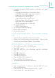
Introduction 1 Chapter 1 - Introduction 1.1 Features and Specifications 1.1.1 Features Chipset VIA® P4M266/VT8233ACD Processor The mainboard is equipped with Socket 478 for installing a Pentium® 4 processor. Intel® Pentium® 4 processor (478-pin) Supports up to 2.2GHz CPU speed 400MHz system data bus System Memory Two 184-pin DDR DIMM sockets Supports up to 2GB using PC1600 (DDR200) / PC2100 (DDR266) unbuffered DDR SDRAM DIMM, 2.
1 Introduction Expansion Slots The mainboard is equipped with 1 universal AGP slot and 3 PCI slots. AGP is an interface designed to support high performance 3D graphics cards. It utilizes a dedicated pipeline to access system memory for texturing, z-buffering and alpha blending. The universal AGP slot supports AGP 2x with up to 533MB/sec. bandwidth and AGP 4x with up to 1066MB/sec . bandwidth for 3D graphics applications. AGP in this mainboard will deliver faster and better graphics to your PC.
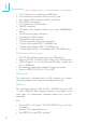
Introduction 1 Integrated Savage4 2D/3D graphics controller and video accelerator - Optimized Shared Memory Architecture (SMA) - 8/16/32MB frame buffer using system memory - Single cycle 128-bit 3D architecture - 8M triangles/second setup engine - 140M pixels/second tri-linear fill rate - Next generation 128-bit 2D graphics engine - High quality DVD video playback - 2D/3D resolutions up to 1920x1440 3D rendering features - MPEG-2 video textures 2D hardware acceleration features Motion video archit
1 Introduction One connector for an external game/MIDI port One connector for external line-out and mic-in jacks Two internal audio connectors (AUX-in and CD-in) One S/PDIF-out connector One connector for IrDA interface Two IDE connectors One floppy drive interface supports up to two 2.
Introduction 1 Supports DMI 2.0 function 2Mbit flash memory Desktop Management Interface (DMI) The mainboard comes with a DMI 2.0 built into the BIOS. The DMI utility in the BIOS automatically records various information about your system configuration and stores these information in the DMI pool, which is a part of the system board's Plug and Play BIOS. DMI, along with the appropriately networked software, is designed to make inventory, maintenance and troubleshooting of computer systems easier.
1 Introduction Wake-On-Ring This feature allows the system that is in the Suspend mode or Soft Power Off mode to wake-up/power-on to respond to calls coming through an internal or external modem. Refer to Wake-On-Ring Connector in chapter 2 and Resume On LAN/Ring (IRQ/Event Activity Detect field) in the Power Management Setup section in chapter 3 for more information. Important: If you are using a modem add-in card, the 5VSB power source of your power supply must support ≥720mA.
Introduction 1 Wake-On-USB Keyboard/Mouse The Wake-On-USB Keyboard/Mouse function allows you to use a USB keyboard or USB mouse to wake up a system that is in the S3 (STR - Suspend To RAM) state. If you are using this function with a device that is connected to the USB 2.0 port, you need to configure 2 jumpers. Refer to Jumper Settings for Wake-On-USB 2.0 Keyboard/Mouse in chapter 2.
1 Introduction With the Suspend to RAM function enabled, you can power-off the system at once by pressing the power button or selecting Standby when you shut down Windows® 98/2000/ME/XP without having to go through the sometimes tiresome process of closing files, applications and operating system. This is because the system is capable of storing all programs and data files during the entire operating session into RAM (Random Access Memory) when it powers-off.
Hardware Installation 2 Chapter 2 - Hardware Installation 2.1 Mainboard Layout KB Mouse PM11-EC/RAMA (Supports onboard audio) J2 CPU fan (J18) DIMM Standby Power LED Wake-On-PS/2 KB/Mouse (JP1) COM 1 (J1) ATX power (J26) Socket 478 COM 2 (J9) Parallel (J4) VGA (CN1) IDE 2 (J23) Game/MIDI (J8) USB 1.
2 Hardware Installation KB Mouse PM11-EL/RAMA (Supports onboard audio and onboard LAN) J2 CPU fan (J18) DIMM Standby Power LED Wake-On-PS/2 KB/Mouse (JP1) COM 1 (J1) ATX power (J26) Socket 478 COM 2 (J9) Parallel (J4) VGA (CN1) IDE 2 (J23) LAN USB 1.
Hardware Installation 2 KB Mouse PM11-UL/RAMA (Supports onboard audio, onboard LAN, USB 2.0 and Smart I/O) J2 CPU fan (J18) DIMM Standby Power LED Wake-On-PS/2 KB/Mouse (JP1) COM 1 (J1) ATX power (J26) Socket 478 COM 2 (J9) Parallel (J4) USB 2.0 USB 2.0 USB 1.
2 Hardware Installation Warning: Electrostatic discharge (ESD) can damage your mainboard, processor, disk drives, add-in boards, and other components. Perform the upgrade instruction procedures described at an ESD workstation only. If such a station is not available, you can provide some ESD protection by wearing an antistatic wrist strap and attaching it to a metal part of the system chassis.
Hardware Installation 2 2.2.1 Installing the DIM Module A DIM module simply snaps into a DIMM socket on the mainboard. Pin 1 of the DIM module must correspond with pin 1 of the socket. Notch Key Tab Tab Pin 1 1. Pull the tabs which are at the ends of the socket to the side. 2. Position the DIMM above the socket with the notch in the module aligned with the key on the socket. 3. Seat the module vertically into the socket. Make sure it is completely seated. The tabs will hold the DIMM in place.
2 Hardware Installation 2.3 Jumper Settings for Clearing CMOS Data 3 2 1 Clear CMOS (JP2) 3 3 2 2 1 1 1-2 On: Normal (default) 2-3 On: Clear CMOS Data Clear CMOS Data - Jumper JP2 If you encounter the following, a) CMOS data becomes corrupted. b) You forgot the keyboard, supervisor or user password. c) You are unable to boot-up the computer system because the processors ratio/clock was incorrectly set in the BIOS. you can reconfigure the system with the default values stored in the ROM BIOS.
Hardware Installation 2 3. Now power-on the system. If your reason for clearing the CMOS data is due to incorrect setting of the processors ratio/clock in the BIOS, please proceed to step 4. 4. After powering-on the system, press to enter the main menu of the BIOS. 5. Select the Frequency/Voltage Control submenu and press . 6. Set the CPU Clock Ratio or CPU Clock field to its default setting or an appropriate frequency ratio or bus clock.
2 Hardware Installation 2.4 Jumper Settings Keyboard/Mouse 3 2 1 for Wake-On-PS/2 Wake-On-PS/2 KB/Mouse (JP1) 3 3 2 2 1 1 1-2 On: Disable - VCC power 2-3 On: Enable - 5VSB power (default) Wake-On-PS/2 Keyboard/Mouse - Jumper JP1 The Wake-On-PS/2 Keyboard/Mouse function allows you to use the PS/2 keyboard or PS/2 mouse to wake up the system from the S5 state. By default, JP1 is enabled.
Hardware Installation 2 2.5 Jumper Settings for Wake-On-USB 2.0 Keyboard/Mouse (PM11-UL/RAMA only) J14 1 2 3 J13 1 2 Wake-On-USB 2.0 KB/Mouse (J13 and J14) 3 1 J14 J14 J13 J13 1-2 On: Enabled 2 3 2-3 On: Disabled (default) Wake-On-USB 2.0 Keyboard/Mouse - J13 and J14 The Wake-On-USB 2.0 Keyboard/Mouse function allows you to use a USB keyboard or USB mouse to wake up a system that is in the S3 (STR - Suspend To RAM) state.
2 Hardware Installation 2.6 Ports and Connectors 2.6.1 Serial Ports COM 1 (J1) 10 9 2 1 COM 2 (J9) COM 1 (Teal/Turquoise) COM 1 Serial Port The built-in serial ports are RS-232C asynchronous communication ports with 16C550A-compatible UARTs that can be used with modems, serial printers, remote display terminals, and other serial devices. You can set the serial ports I/O address in the Integrated Peripherals submenu (Super IO Device field) of the BIOS.
Hardware Installation 2 One card-edge bracket, mounted with a serial port cable and a game/MIDI port cable, is provided with the system board. If you want to use the secondary serial port, connect the serial port cable to connector J9. Make sure the colored stripe on the ribbon cable is aligned with pin 1 of connector J9. Mount the card-edge bracket to the system chassis.
2 Hardware Installation 2.6.2 PS/2 Mouse and PS/2 Keyboard Ports J2 PS/2 Mouse PS/2 Keyboard Mouse (Green) KB (Purple) The mainboard is equipped with an onboard PS/2 mouse (Green) and PS/2 keyboard (Purple) ports - both at location J2 of the ATX double deck ports of the mainboard. The PS/2 mouse port uses IRQ12. If a mouse is not connected to this port, the system will reserve IRQ12 for other expansion cards.
Hardware Installation 2 2.6.3 Parallel Port J4 Parallel (Burgundy) Parallel Port The mainboard has a standard parallel port (J4 - Burgundy) located at the ATX double deck ports of the board for interfacing your PC to a parallel printer. It supports SPP, ECP and EPP modes. You can select the ports mode in the Integrated Peripherals submenu (Super IO Device field) of the BIOS.
2 Hardware Installation Setting 28 Function SPP (Standard Parallel Port) Allows normal speed operation but in one direction only. ECP (Extended Capabilities Port) Allows parallel port to operate in bidirectional mode and at a speed faster than the SPPs data transfer rate. EPP (Enhanced Parallel Port) Allows bidirectional parallel port operation at maximum speed.
Hardware Installation 2 2.6.4 Floppy Disk Drive Connector 34 33 FDD (J27) 2 1 The mainboard is equipped with a shrouded floppy disk drive connector that supports two standard floppy disk drives. To prevent improper floppy cable installation, the shrouded floppy disk header has a keying mechanism. The 34-pin connector on the floppy cable can be placed into the header only if pin 1 of the connector is aligned with pin 1 of the header.
2 Hardware Installation 2.6.5 IDE Disk Drive Connector 40 39 IDE 2 (J23) IDE 1 (J19) 2 1 The mainboard is equipped with two shrouded PCI IDE headers that will interface four Enhanced IDE (Integrated Drive Electronics) disk drives. To prevent improper IDE cable installation, each shrouded PCI IDE header has a keying mechanism. The 40-pin connector on the IDE cable can be placed into the header only if pin 1 of the connector is aligned with pin 1 of the header.
Hardware Installation 2 Adding a Second IDE Disk Drive When using two IDE drives, one must be set as the master and the other as the slave. Follow the instructions provided by the drive manufacturer for setting the jumpers and/or switches on the drives. The mainboard supports Enhanced IDE or ATA-2, ATA/33, ATA/66, ATA/100 and ATA/133 hard drives. We recommend that you use hard drives from the same manufacturer.
2 Hardware Installation 2.6.6 Universal Serial Bus Ports 2.6.6.1 PM11-EC/RAMA and PM11-EL/RAMA CN2 USB 1.1 (J17) 11 15 1 5 USB 1.1 (Black) The PM11-EC/RAMA and PM11-EL/RAMA mainboards are each equipped with two onboard USB 1.1 ports (CN2 - Black) located at the ATX double deck ports of the board. Depending on the type of USB port cable that you are using, the J17 connector on the mainboard allows you to connect 2 more optional USB 1.1 ports. These optional USB 1.
Hardware Installation 2 2.6.6.2 PM11-UL/RAMA JUSB1 CN2 USB 1.1 (J17) USB 2.0 (J12) 2 1 10 9 USB 2.0 (Black) 11 15 1 5 USB 1.1 (Black) The PM11-UL/RAMA mainboard is equipped with two onboard USB 2.0 ports (JUSB1 - Black) and two onboard USB 1.1 ports (CN2 - Black) located at the ATX double deck ports of the board. It is also equipped with a J12 connector for additional external USB 2.0 ports and a J17 connector for additional external USB 1.1 ports.
2 Hardware Installation USB 1.1 (J17) Pin Function Pin Function Pin Function 1 VCC 6 VCC 11 Ground 2 UP2- 7 UP3- 12 Ground 3 UP2+ 8 UP3+ 13 UP2+ 4 Ground 9 Ground 14 UP2- 5 Key 10 Ground 15 VCC USB 2.
Hardware Installation 2 2.6.7 RJ45 Fast-Ethernet Port (PM11-EL/RAMA and PM11-UL/RAMA only) CN2 LAN RJ45 LAN RJ45 LAN The PM11-EL/RAMA and PM11-UL/RAMA mainboards are each equipped with an onboard RJ45 fast-ethernet LAN port at location CN2 of the ATX double deck ports. It allows the mainboard to connect to a local area network by means of a network hub. You may enable or disable the onboard LAN in the Integrated Peripherals submenu (VIA OnChip PCI Device field) of the BIOS.
2 Hardware Installation 2.6.8 VGA Port CN1 VGA (Blue) VGA Port The system board can only be used with an analog video monitor. Connect the monitors 15-pin D-shell cable connector to the VGA port (CN1 - Blue) located at the ATX double deck ports of the board. If your monitor supports analog video but does not have a 15-pin D-shell connector, see your monitor dealer for the adapter or optional cable.
Hardware Installation 2 2.6.9 IrDA Connector IrDA (J10) 1 2 3 4 5 Pin Function 1 VCC 2 N. C. 3 IRRX 4 Ground 5 IRTX The mainboard is equipped with an IrDA connector for wireless connectivity between your computer and peripheral devices. The IRDA (Infrared Data Association) specification supports data transfers of 115K baud at a distance of 1 meter. Connect your IrDA cable to connector J10 on the mainboard.
2 Hardware Installation 2.6.10 CPU Fan Connector 1 2 3 CPU fan (J18) Pin Function 1 Ground 2 Power 3 Sense The processor must be kept cool by using a fan with heatsink. Connect the CPU fan to the 3-pin fan connector at location J18 on the mainboard. The system is capable of monitoring the speed of the CPU fan.
Hardware Installation 2 2.6.11 Chassis Fan Connector 3 2 1 Pin Function 1 On/Off 2 +12V 3 Sense Chassis fan (J28) If you are installing a chassis fan in the system unit, connect the fans connector to location J28 on the mainboard. The fan will provide adequate airflow throughout the chassis to prevent overheating the processor. The system is capable of monitoring and controlling the speed of the chassis fan. The chassis fan will automatically turn off once the system enters the Suspend mode.
2 Hardware Installation 2.6.12 Chip Fan Connector 1 2 Chip fan (J11) Pin Function 1 +12V 2 Ground The VIA P4M266 chip must be kept cool by using a fan with heatsink. Connect the fans connector to location J11 on the system board.
Hardware Installation 2 2.6.13 Game/MIDI Port 1 15 2 Game/MIDI (J8) The system board is equipped with a 15-pin connector at location J8 for connecting an external game/MIDI port. One card-edge bracket, mounted with a serial port cable and a game/MIDI port cable, is provided with the system board. Install the card-edge bracket to the system chassis then connect the game/MIDI port cable to connector J8. Make sure the colored stripe on the ribbon cable is aligned with pin 1 of connector J8.
2 Hardware Installation 2.6.14 Audio Jacks CN3 2 1 10 9 Front audio (J3) Mic-In (Pink) Line-In (Light Blue) Line-Out (Lime) Front Audio (J3) Pin 42 Function Pin Function 1 Mic+ 2 Ground 3 Mic Power 4 AuD_Vcc (Avcc) 5 AuD_R_Out 6 AuD_R_Return (GND) 7 N. C.
Hardware Installation 2 Onboard Audio Jacks (CN3) The mainboard is equipped with 3 audio jacks. A jack is a one-hole connecting interface for inserting a plug. Line-out Jack (Lime) This jack is used to connect external speakers for audio output from the mainboard. Line-in Jack (Light Blue) This jack can be connected to the line-out jack of any external audio devices such as Hi-fi set, CD player, AM/FM radio tuner, synthesizer, etc.
2 Hardware Installation 2.6.15 Internal Audio Connectors CD-in (J6) AUX-in (J7) 1 2 3 4 Pin Function 1 Left audio channel 2 Ground 3 Ground 4 Right audio channel AUX-in and CD-in These connectors are used to receive audio from a CD-ROM drive, TV tuner or MPEG card.
Hardware Installation 2 2.6.16 S/PDIF-out Connector 1 2 3 4 S/PDIF-out (J5) Pin Function 1 AVDD5 2 N. C . 3 SPDIF 4 Ground The mainboard is equipped with a digital audio interface - S/PDIF (Sony/Philips Digital Interface). S/PDIF is a standard audio file transfer format that transfers digital audio signals to a device without having to be converted first to an analog format. This prevents the quality of the audio signal from degrading whenever it is converted to analog.
2 Hardware Installation 2.6.17 Smart I/O Connectors (PM11-UL/RAMA only) SD (J20) MS (J24) 10 1 10 5 SC (J25) 6 1 The PM11-UL/RAMA mainboard is equipped with a security interface - Smart Card (SC) interface and two compact storage interfaces - Memory Stick (MS) interface and Secure Digital Memory Card (SD) interface. An optional device will be provided allowing you to insert these cards.
Hardware Installation 2 The optional Smart I/O Drive Secure Digital Memory Card Memory Stick Smart Card 47
2 Hardware Installation Smart Card Interface Pin Function Pin Function 1 VCC 6 Ground 2 SCAPWC- 7 SCARST- 3 SCAC4 8 SCALED 4 SCAIO 9 SCAC8 5 SCACLK 10 SCAPSNT Memory Stick Interface Pin Function Pin Function 1 Ground 6 MSA4 2 MSA1 7 MSA5 3 VCC3 8 MSACLK 4 MSA2 9 MSAPWC- 5 MSA3 10 MSALED Secure Digital Memory Card Interface Pin 48 Function Pin Function 1 Ground 6 MSB4 2 MSB1 7 MSB5 3 VCC3 8 MSBCLK 4 MSB2 9 MSBPWC- 5 MSB3 10 MSBLED
Hardware Installation 2 2.6.18 Wake-On-LAN Connector 321 Wake-On-LAN (J7) Pin Function 1 WOL 2 Ground 3 +5VSB The mainboard supports the Wake-On-LAN function. This function will allow the network to remotely power-on a Soft Power Down (Soft-Off) PC. However, if your system is in the Suspend mode, you can power-on the system only through an IRQ or DMA interrupt.
2 Hardware Installation 2.6.19 Wake-On-Ring Connector 2 1 Pin Function 1 Ground 2 RI# Wake-On-Ring (J16) The Wake-On-Ring connector is used to connect to an internal modem card that has the same connector. It will allow the system that is in the Suspend mode or Soft Power Off mode to wake-up/ power-on to respond to calls coming through the internal modem card.
Hardware Installation 2 2.6.20 DIMM and PCI Standby Power LEDs DIMM Standby Power LED PCI Standby Power LED DIMM Standby Power LED This LED will turn red when the systems power is on or when it is in the Suspend state (Power On Suspend or Suspend to RAM). It will not light when the system is in the Soft-Off state. PCI Standby Power LED This LED will turn red when the system is in the power-on, Soft-Off or Suspend (Power On Suspend or Suspend to RAM) state.
2 Hardware Installation 2.6.21 Power Connectors +12V power (ATXP1) 2 1 4 3 10 20 1 11 ATX power (J26) We recommend that you use a power supply that complies with the ATX12V Power Supply Design Guide Version 1.1. Connect the ATX12V power supplys 20-pin ATX main power connector and 4-pin +12V power connector to J26 and ATXP1 respectively. The 4-pin +12V power connector enables the delivery of more +12VDC current to the processors Voltage Regulator Module (VRM).
Hardware Installation 2 ATX Main Power Connector Pin Function Pin Function 1 3.3V 11 3.3V 2 3.
2 Hardware Installation 2.6.22 Front Panel Connectors Front panel connectors (J21) HD-LED: Primary/Secondary IDE LED This LED will light when the hard drive is being accessed. G-LED: Green LED This LED will not light when the systems power is on or when the system is in the S3 (STR - Suspend To RAM) state. It will light when the system is in the S1 (POS - Power On Suspend) state.
Hardware Installation 2 PWR-LED: Power/Standby LED When the systems power is on, this LED will light. When the system is in the S1 (POS - Power On Suspend) state, it will blink every second. When the system is in the S3 (STR - Suspend To RAM) state, it will blink every 4 seconds. Note: If your system did not boot-up and the Power/Standby LED did not light after it was powered-on, it may indicate that the CPU or memory module was not installed properly.
3 Award BIOS Setup Utility Chapter 3 - Award BIOS Setup Utility 3.1 The Basic Input/Output System The Basic Input/Output System (BIOS) is a program that takes care of the basic level of communication between the processor and peripherals. In addition, the BIOS also contains codes for various advanced features found in this mainboard. This chapter explains the Setup Utility for the Award BIOS. After you power up the system, the BIOS message appears on the screen and the memory count begins.
Award BIOS Setup Utility 3 Phoenix - AwardBIOS CMOS Setup Utility Standard CMOS Features u u u u Date (mm:dd:yy) Time (hh:mm:ss) Tue, Feb 5 2002 4 : 35 : 5 IDE IDE IDE IDE Press Press Press Press Primary Master Primary Slave Secondary Master Secondary Slave Enter Enter Enter Enter None None None None Drive A Drive B 1.44M, 3.5 in.
3 Award BIOS Setup Utility IDE Primary/Secondary Master/Slave If you wish to define your own drive type manually, select Manual. The drive type information should be included in the documentation from your hard disk vendor. If you select Auto, the BIOS will auto-detect the HDD & CD-ROM drive at the POST stage and show the IDE for the HDD & CD-ROM drive. If a hard disk has not been installed, select None. Capacity Displays the approximate capacity of the disk drive.
Award BIOS Setup Utility 3 Halt On This field determines whether the system will stop if an error is detected during power up. The default setting is All Errors. No Errors The system boot will not stop for any errors detected. All Errors The system boot will stop whenever the BIOS detects a non-fatal error. All, But Keyboard The system boot will not stop for a keyboard error; it will stop for all other errors.
3 Award BIOS Setup Utility 3.1.2 Advanced BIOS Features The Advanced BIOS Features allows you to configure your system for basic operation. Some entries are defaults required by the mainboard, while others, if enabled, will improve the performance of your system or let you set some features according to your preference.
Award BIOS Setup Utility 3 field. Also, disable this field if you are installing or running certain operating systems like Windows ® 98/2000/ME/XP or the operating system may not install nor work. CPU L1 & L2 Cache These fields speed up the memory access. The default value is enabled. CPU L2 Cache ECC Checking The processors supported by the mainboard come with built-in Level 2 cache. By default, ECC is enabled to check the Level 2 cache. If you are not using this function, set this field to Disabled.
3 Award BIOS Setup Utility Boot Up Floppy Seek When enabled, the BIOS will check whether the floppy disk drive installed is 40 or 80 tracks. Note that the BIOS cannot distinguish between 720K, 1.2M, 1.44M and 2.88M drive types as they are all 80 tracks. When disabled, the BIOS will not search for the type of floppy disk drive by track number. Note that there will not be any warning message if the drive installed is 360KB.
Award BIOS Setup Utility 3 Security Option This field determines when the system will prompt for the password - everytime the system boots or only when you enter the BIOS setup. Set the password in the Set Supervisor/User Password submenu. System The system will not boot and access to Setup will be denied unless the correct password is entered at the prompt. Setup The system will boot, but access to Setup will be denied unless the correct password is entered at the prompt.
3 Award BIOS Setup Utility 3.1.
Award BIOS Setup Utility 3 DRAM Clock This field is used to select the clock speed of the DIMM. By SPD 100 MHz 133 MHz The EEPROM on a DIMM has SPD (Serial Presence Detect) data structure that stores information about the module such as the memory type, memory size, memory speed, etc. When this option is selected, the system will run according to the information in the EEPROM. The memory clock speed will run at 200MHz. The memory clock speed will run at 266MHz.
3 Award BIOS Setup Utility Active to Precharge (Tras) The options are 5T and 6T. Active to CMD (Trcd) The options are 2T and 3T. DRAM Burst Len The options are 4 and 8. DRAM Command Rate The options are 1T Command and 2T Command. AGP & P2P Bridge Control Move the cursor to this field and press . The following fields will appear. AGP Aperture Size This field is relevant to the memory-mapped graphics data of the AGP card installed in your system. Leave this in its default setting, which is 128M.
Award BIOS Setup Utility 3 AGP Master 1 WS Read Set this field to Enabled to add one clock tick to AGP read operations. CPU & PCI Bus Control Move the cursor to this field and press . The following fields will appear. CPU to PCI Write Buffer Enabled Writes from the CPU to the PCI bus are buffered to offset the speed difference between the CPU and PCI bus. Disabled Writes are not buffered therefore the CPU must wait until the write cycle is complete before starting another write cycle.
3 Award BIOS Setup Utility Video RAM Cacheable When enabled, it allows the video RAM to be cacheable thus providing better video performance. If your graphics card does not support this function, leave this field in its default setting. VGA Share Memory Size This field is used to select the memory size that will be shared by the VGA. FB Address Conversion The options are Enabled and Disabled. FB Page Close Prediction The options are Enabled and Disabled.
Award BIOS Setup Utility 3 3.1.4 Integrated Peripherals Phoenix - AwardBIOS CMOS Setup Utility Integrated Peripherals u u u VIA OnChip IDE Device VIA OnChip PCI Device Super IO Device Init Display First OnChip USB1.
3 Award BIOS Setup Utility complete task by themselves. Your system supports five modes, 0 (default) to 4, which primarily differ in timing. When Auto is selected, the BIOS will select the best available mode after checking your drive. Auto Mode 0-4 The BIOS will automatically set the system according to your hard disk drives timing. You can select a mode that matches your hard disk drives timing. Caution: Do not use the wrong setting or you will have drive errors.
Award BIOS Setup Utility 3 Super IO Device Move the cursor to this field and press . The following fields will appear. Onboard FDC Controller Enabled Enables the onboard floppy disk controller. Disabled Disables the onboard floppy disk controller. Onboard Serial Port 1 and Onboard Serial Port 2 Auto The system will automatically select an I/O address for the onboard serial port 1 and serial port 2.
3 Award BIOS Setup Utility UART Mode Select The mainboard supports IrDA function for wireless connectivity between your computer and peripheral devices. You may not use IrDA (J10) and the COM 2 (J9) serial port at the same time. If you are using the COM 2 serial port, make sure this field is set to Normal. To use the IrDA function, follow the steps below. 1. Connect your IrDA cable to connector J10 on the mainboard. 2.
Award BIOS Setup Utility 3 Parallel Port Mode The options are SPP, EPP, ECP and ECP+EPP. These apply to standard specifications and will depend on the type and speed of your device. Refer to your peripherals manual for the best option. SPP Allows normal speed operation but in one direction only. ECP (Extended Capabilities Port) Allows parallel port to operate in bidirectional mode and at a speed faster than the normal modes data transfer rate.
3 Award BIOS Setup Utility OnChip USB1.1 Controller This field is used to select the USB 1.1 ports you want Enabled. USB Keyboard Support By default, USB Keyboard Support is Disabled. However, if you are using a USB keyboard under DOS, make sure to enable this function. USB Mouse Support This field is used to enable or disable the USB mouse. IDE HDD Block Mode Enabled The IDE HDD uses the block mode. The system BIOS will check the hard disk drive for the maximum block size the system can transfer.
Award BIOS Setup Utility 3 3.1.5 Power Management Setup The Power Management Setup allows you to configure your system to most effectively save energy.
3 Award BIOS Setup Utility Power Management Option This field allows you to select the type (or degree) of power saving by changing the length of idle time that elapses before the Suspend Mode field is activated. Min Saving Max Saving User Define Minimum power saving time for Suspend mode = 1 hr. Maximum power saving time for Suspend mode = 1 min. Allows you to set the power saving time in the Suspend Mode field.
Award BIOS Setup Utility 3 MODEM Use IRQ This field is used to set an IRQ channel for the modem installed in your system. Soft-Off by PWRBTN This field allows you to select the method of powering off your system. Delay 4 Sec Regardless of whether the Power Management field is enabled or disabled, if the power button is pushed and released in less than 4 sec, the system enters the Suspend mode.
3 Award BIOS Setup Utility IRQ/Event Activity Detect Move the cursor to this field and press . The following fields will appear. PS2KB Wakeup Select Password To use a password to wake up the system, select this option then press . Enter your password. You can enter up to 5 characters. Type in exactly the same password to confirm, then press . Important: If you forgot the password, you must power-off the system, unplug the power cord and clear the CMOS data.
Award BIOS Setup Utility 3 Resume on PCI Event If you are using the Wake-On-USB Keyboard/Mouse function with a device that is connected to the USB 2.0 port, set this field to Enabled. This function allows you to use a USB keyboard or USB mouse to wake up a system that is in the S3 (STR Suspend To RAM) state. You must also set this field to Enabled if your PCI card such as LAN card or modem card uses the PCI PME (Power Management Event) signal to remotely wake up the PC.
3 Award BIOS Setup Utility Date (of Month) 0 The system will power-on everyday according to the time set in the Resume Time (hh:mm:ss) field. 1-31 Select a date you would like the system to power-on. The system will power-on on the set date, and time set in the Resume Time (hh:mm:ss) field. Resume Time (hh:mm:ss) This is used to set the time you would like the system to poweron.
Award BIOS Setup Utility 3 3.1.6 PnP/PCI Configurations This section shows how to configure the PCI bus system. It covers some very technical items and it is strongly recommended that only experienced users should make any changes to the default settings.
3 Award BIOS Setup Utility IRQ Resources Move the cursor to this field and press . The IRQ-3 to IRQ-15 fields will appear. Set each system interrupt to either PCI Device or Reserved. PCI/VGA Palette Snoop This field determines whether the MPEG ISA/VESA VGA cards can work with PCI/VGA or not. The default value is Disabled. Enabled MPEG ISA/VESA VGA cards work with PCI/VGA. Disabled MPEG ISA/VESA VGA cards does not work with PCI/ VGA.
Award BIOS Setup Utility 3 PCI Slot 1 Use IRQ to PCI Slot 3 Use IRQ By default, an IRQ is automatically assigned to the PCI devices that are installed in the PCI slots. If a PCI device has not been assigned an IRQ, you must manually assign an IRQ for the device. During system boot-up, you will see NA for the device that does not have an IRQ assigned.
3 Award BIOS Setup Utility 3.1.7 PC Health Status Phoenix - AwardBIOS CMOS Setup Utility PC Health Status CPU Warning Temperature Current System Temp. Current CPU Temperature Current CPU FAN Speed Current Chassis FAN Speed CPU(V) +3.3 V +5 V +12 V -12 V -5 V VBAT(V) 5VSB(V) Warning_Beep Item Help Disabled 27C/80F 37C/98F 0 RPM 0 RPM 1.75 V 3.35 V 4.90 V 11.85 V -11.45 V -5.14 V 3.24 V 5.
Award BIOS Setup Utility 3 +3.3V, +5V, +12V, -12V, -5V, VBAT(V) and 5VSB(V) These fields show the output voltage of the power supply. Warning_Beep Set this field to Enabled so that the warning alarm will beep when the CPUs temperature exceeded the limit set in the CPU Warning Temperature field.
3 Award BIOS Setup Utility 3.1.8 Frequency/Voltage Control Phoenix - AwardBIOS CMOS Setup Utility Frequency/Voltage Control CPU Clock Auto Detect PCI/DIMM Clk Spread Spectrum CPU Clock Ratio 100MHz Enabled Disabled 8X ↑↓→← Move Enter:Select +/-/PU/PD:Value F10:Save F5:Previous Values F6:Fail-Safe Defaults Item Help Menu Level ESC:Exit F1:General Help F7:Optimized Defaults The settings on the screen are for reference only. Your version may not be identical to this one.
Award BIOS Setup Utility 3 CPU Clock Ratio This field is used to select the CPUs frequency ratio. Important: The frequency ratio of some processors may have been locked by the manufacturer. If you are using this kind of processor, setting an extended ratio for the processor will have no effect. The system will instead use its factor y default ratio.
3 Award BIOS Setup Utility 3.1.9 Load Fail-Safe Defaults The Load Fail-Safe Defaults option loads the troubleshooting default values permanently stored in the ROM chips. These settings are not optimal and turn off all high performance features. You should use these values only if you have hardware problems. Highlight this option in the main menu and press . The message below will appear. Load Fail-Safe Defaults (Y/N)? N If you want to proceed, type and press .
Award BIOS Setup Utility 3 3.1.11 Set Supervisor Password If you want to protect your system and setup from unauthorized entry, set a supervisors password with the System option selected in the Advanced BIOS Features. If you want to protect access to setup only, but not your system, set a supervisors password with the Setup option selected in the Advanced BIOS Features. You will not be prompted for a password when you cold boot the system.
3 Award BIOS Setup Utility 3.1.13 Save & Exit Setup When all the changes have been made, highlight Save & Exit Setup and press . The message below will appear: Save to CMOS and Exit (Y/N)? N Type Y and press . The modifications you have made will be written into the CMOS memory, and the system will reboot. You will once again see the initial diagnostics on the screen.
Supported Software 4 Chapter 4 - Supported Software 4.1 Desktop Management Interface (DMI) The mainboard comes with a DMI built into the BIOS. DMI, along with the appropriately networked software, is designed to make inventory, maintenance and troubleshooting of computer systems easier. With DMI, a network administrator or MIS engineer can remotely access some information about a particular computer system without physically going to it.
4 Supported Software 4.1.
Supported Software 4 Add DMI 1. Use the ← or → arrow keys to select the Add DMI menu. 2. Highlight the item on the left screen that you would like to add by using the ↑ or ↓ arrow keys, then press . 3. The cursor will move to the screen you select allowing you to enter information about the added item. 4. Press to save information into the flash ROM. To view information about the added items, go to the Edit DMI menu. Load DMI File 1.
4 Supported Software 4.2 Hardware Monitor The mainboard comes with the Hardware Monitor utility contained in the provided CD. It is capable of monitoring the systems hardware conditions such as the temperature of the CPU and system, voltage, and speed of the CPU and chassis fans. It also allows you to manually set a range to the items being monitored. If the values are over or under the set range, a warning message will pop-up.
Supported Software 4 VIA Service Pack Installation Notes The AGP VxD Driver and VIA INF Driver drivers in the VIA Service Pack are supported in Windows® 98, Windows® 98 SE, Windows® ME and Windows® 2000. You must first install the VIA Service Pack prior to installing any other drivers. However, this may not be the case for some AGP cards. Please read carefully the following information. Important: The VGA driver that came with some AGP cards is already bundled with the AGP VxD driver.
4 Supported Software 4.4 Audio Drivers and Software Applications The CD in the mainboard package also includes audio drivers and audio playback software for Windows 98, Windows 98 SE, Windows ME, Windows NT 4.0 and Windows 2000 operating systems. For installation instructions or information about their corresponding readme, click the Read Me button in the autorun screen. The autorun screen normally appears after the CD is inserted into a CD-ROM drive. 1.
Supported Software 4 4.6 Graphics Drivers 1. Insert the CD that came with the system board package into a CD-ROM drive. The autorun screen (Main Board Utility CD) will appear. 2. Click VIA VGA Driver. 3. Follow the prompts on the screen to complete installation. 4. Restart the system. 4.7 VIA USB 2.0 Driver (PM11-UL/RAMA only) If you are using a USB device that is connected to the USB 2.0 port, you must install the VIA USB 2.
4 Supported Software Winbond SmartCard Application button to install the application. Refer to its readme file for instructions on using the application. 4.10 Microsoft DirectX 8.1 Driver 1. Insert the CD that came with the mainboard package into a CD-ROM drive. The autorun screen (Main Board Utility CD) will appear. 2. Click Microsoft DirectX 8.1 Driver. 3. Click Yes to continue. 4. Follow the prompts on the screen to complete installation. 5. Restart the system. 4.
Using the Suspend to RAM Function A Appendix A - Using the Suspend to RAM Function A.1 Using the Suspend to RAM Function If you are using the Windows® 98 operating system, please follow the steps below. 1. Select Power Management Setup in the main menu screen and press . 2. In the ACPI Function field, select Enabled. 3. In the ACPI Suspend Type field, select S3(STR).
A Using the Suspend to RAM Function 7. Boot Windows® 98. In the Windows ® 98 desktop, click the Start button. Move the cursor to Settings, then click Control Panel. To check whether ACPI was properly installed, double-click the System icon. In the System Properties dialog box, click the Device Manager tab. In View devices by type, click System devices. 8. 100 Double-click the System icon. In the System Properties dialog box, click the Performance tab.
Using the Suspend to RAM Function 9. A Click File System. In the Typical role of this computer field, select Mobile or docking system. Click Apply, then click OK. Restart the computer. 10. Repeat step 7 to open the Control Panel dialog box. Doubleclick the Power Management icon. 11. Click the Advanced tab. In the When I press the power button on my computer field, select Standby.
A Using the Suspend to RAM Function 12. After completing the steps above and you want to power-off the computer, you do not need to go through the process of closing files, applications and operating system. You can poweroff the computer at once by pressing the power button or selecting Standby when you shut down Windows® 98. To power-on the computer, just press the power button. The operating session where you left off when you power-off the computer will resume in not more than 8 seconds.
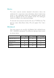
System Error Message B Appendix B - System Error Message When the BIOS encounters an error that requires the user to correct something, either a beep code will sound or a message will be displayed in a box in the middle of the screen and the message, PRESS F1 TO CONTINUE, CTRL-ALT-ESC or DEL TO ENTER SETUP, will be shown in the information box at the bottom. Enter Setup to correct the error. B.1 POST Beep There are two kinds of beep codes in the BIOS.
B System Error Message setting than indicated in Setup. Determine which setting is correct, either turn off the system and change the jumper or enter Setup and change the VIDEO selection. FLOPPY DISK(S) fail (80) Unable to reset floppy subsystem. FLOPPY DISK(S) fail (40) Floppy type mismatch. Hard Disk(s) fail (80) HDD reset failed. Hard Disk(s) fail (40) HDD controller diagnostics failed. Hard Disk(s) fail (20) HDD initialization error. Hard Disk(s) fail (10) Unable to recalibrate fixed disk.
Troubleshooting C Appendix C - Troubleshooting C.1 Troubleshooting Checklist This chapter of the manual is designed to help you with problems that you may encounter with your personal computer. To efficiently troubleshoot your system, treat each problem individually. This is to ensure an accurate diagnosis of the problem in case a problem has multiple causes. Some of the most common things to check when you encounter problems while using your system are listed below. 1.
C Troubleshooting The picture seems to be constantly moving. 1. The monitor has lost its vertical sync. Adjust the monitors vertical sync. 2. Move away any objects, such as another monitor or fan, that may be creating a magnetic field around the display. 3. Make sure your video cards output frequencies are supported by this monitor. The screen seems to be constantly wavering. 1. If the monitor is close to another monitor, the adjacent monitor may need to be turned off.
Troubleshooting C Hard Drive Hard disk failure. 1. Make sure the correct drive type for the hard disk drive has been entered in the BIOS. 2. If the system is configured with two hard drives, make sure the bootable (first) hard drive is configured as Master and the second hard drive is configured as Slave. The master hard drive must have an active/bootable partition. Excessively long formatting period. 1.
C Troubleshooting Serial Port The serial device (modem, printer) doesnt output anything or is outputting garbled characters. 1. Make sure that the serial devices power is turned on and that the device is on-line. 2. Verify that the device is plugged into the correct serial port on the rear of the computer. 3. Verify that the attached serial device works by attaching it to a serial port that is working and configured correctly.